

System and method to simulate hemodynamics
a hemodynamic pattern and system technology, applied in the field of system and method for simulating can solve the problems of reducing blood flow, affecting the hemodynamic pattern of physiologic blood flow, affecting the hemodynamic pattern of physiologic blood flow, etc., and causing death, ischemia, and ischemia
- Summary
- Abstract
- Description
- Claims
- Application Information
AI Technical Summary
Benefits of technology
Problems solved by technology
Method used
Image

Examples
example 1
Preparation of Silicone Tubing for Attachment and Growth of Endothelial Cells
[0118]In this example, the vessel chosen for growth of endothelial cells is a silicone tubing, sold by Dow-Corning, Midland, Mich. under the brand name of SYLGARD 184 elastomer, or Silastic (MDX4-4210), Medical Grade tubing, and used to prepare elastic artery models. These models were prepared using the method described by Lee and Tarbell (1997, and hereby incorporated by reference), and included the preparation of models of human linear and bifurcating arteries.
[0119]For the preparation of linear elastic vessels, a pair of symmetric, half-cylindrical grooved molds made of a plastic, such as PLEXIGLASS, are machined to have a diameter that matches the inner diameter of the elastic model described above. In one preferred embodiment, the linear elastic vessels have a length of approximately 29 centimeters and an inner diameter of approximately 0.79 centimeters, in another embodiment of the present invention, ...
example 2
Tissue Culture Conditions
[0122]Endothelial cells (“ECs”) were obtained either from bovine aortas (“BAECs”), or from human umbilical veins (“HUVECs”), and cultured by growth as primary cultures, using procedures described in Sill et al. (1995). the contents of which is hereby incorporated by reference.
[0123]The BAECs were the cells most commonly used with the present invention. An inoculum of between 60,000–80,000 cells per square centimeter is used twice, once to enable the cells to adhere to the surface of the vessel for a 45 minute time period, and a second time after rotating the position of the vessel 180 degrees to enable the vessel's other side to become coated. The cells are grown in a monolayer until confluency is achieved, in a 37 degree centrigrade tissue culture incubator in an atmosphere of 5% CO2 in air. The preferred growth medium 16 is Dulbecco's Modified Eagle's Medium (“DMEM”, obtained commercially from Sigma Chemical Corp., St. Louis, Mo.), containing 10% Fetal Bov...
example 3
Effect of Different Stress Phase Angles: Zero Degree SPA
[0126]FIG. 2 is a plot of the diameter (circles) and pressure (triangles) waveforms as a function of time with a zero degree stress phase angle (SPA) difference.
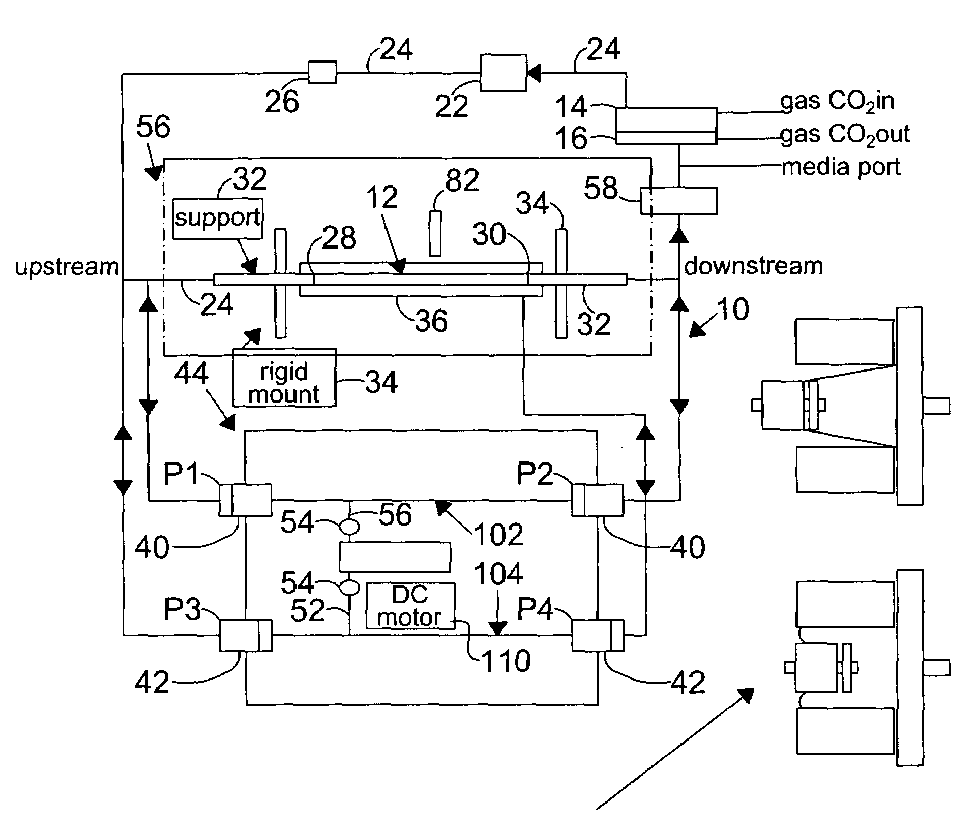
[0127]Changes in the diameter of the compliant vessel 12 can be measured by one of several methods known to those skilled in the art. These include the use of such non-contacting methods as ultrasound or laser light, or the use of an elastic strain gauge, which is in physical contact with the specimen (the compliant vessel). In the present invention, the preferred method of monitoring the changes in compliant vessel diameter is with an ultrasound transducer (Panametrics Co., not shown) which is mounted through the exterior chamber wall and which is focused on the compliant vessel.
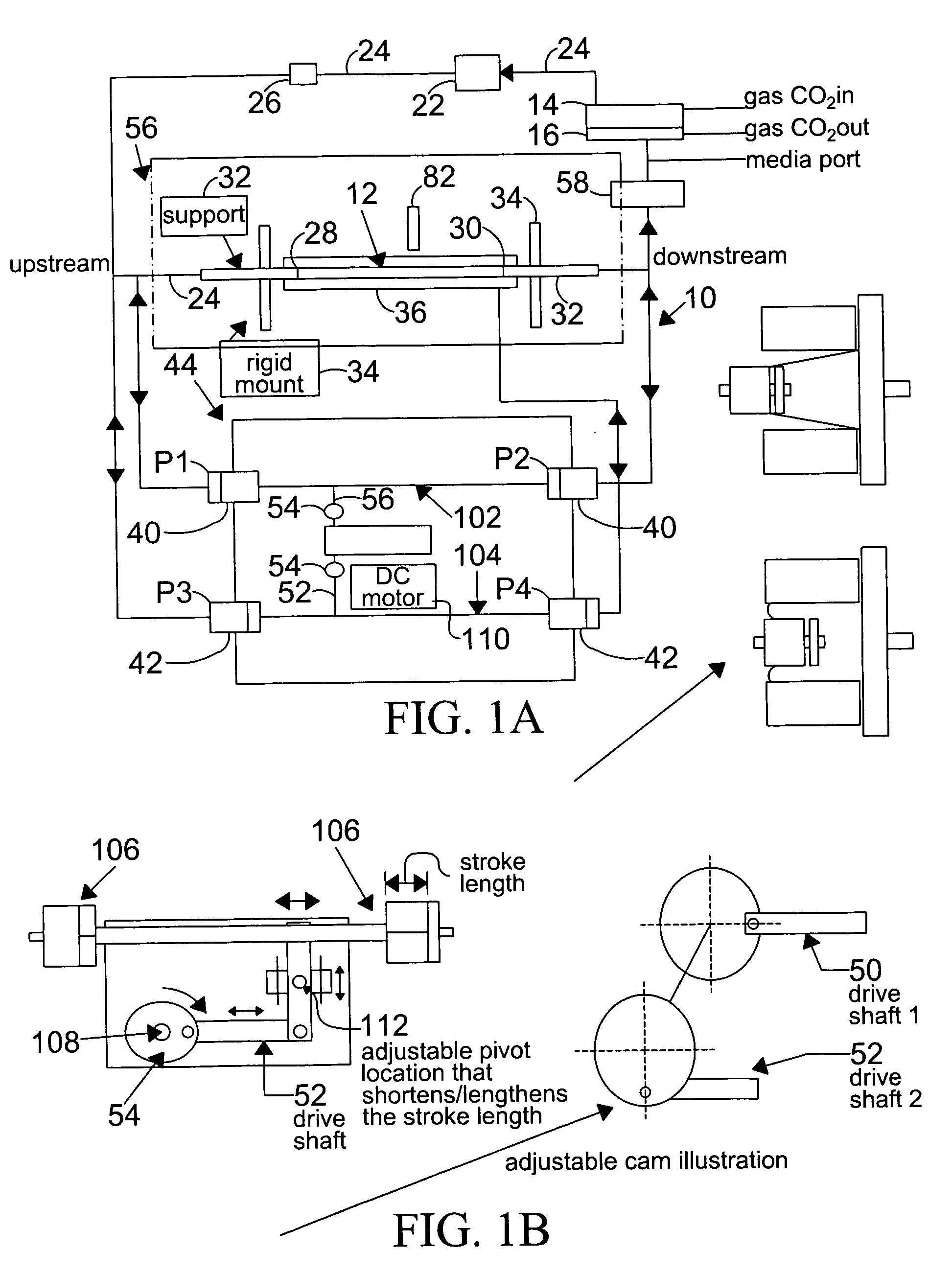
[0128]The computer controlled drive unit 44 is capable of generating different waveforms, which can range from a sine wave, as employed in this and the subsequent examples (FIGS.2–6), or which ...
PUM
 Abstract
Description
Claims
Application Information