Positive resist composition

Inactive Publication Date: 2006-11-21
FUJIFILM HLDG CORP +1
View PDF10 Cites 4 Cited by
  • Summary
  • Abstract
  • Description
  • Claims
  • Application Information

AI Technical Summary

Benefits of technology

[0012]Accordingly, a purpose of the invention is to provide a positive resist composition suitably used for the exposure source having a wave length of not more than 160 nm, particularly F2 excimer laser beam (157 nm), and is more specifically to provide a positive resist composition exhibiting a sufficient transparency to 157 nm region radiations as well as desirable coating property and developing performances free of development defect.

Problems solved by technology

Since the conventional novolac resin and naphthoquinonediazide-based resist exhibits a strong absorption in the deep UV region around 248 nm, the deep UV light is difficult to reach the bottom portion of the resist, thus giving patterns having a tapered cross-section, requiring a large amount of exposure.
In the case of using the ArF excimer laser light (193 nm), the chemically amplified resists did not show satisfactory performance since compounds having an aromatic group exhibit a strong absorption at the 193 nm wavelength region.
However, the resist based on these fluorine-containing resins sometimes exhibit insufficient levels of resistance against dry etching.

Method used


Image

  • Positive resist composition
  • Positive resist composition
  • Positive resist composition

Examples


synthetic example 1

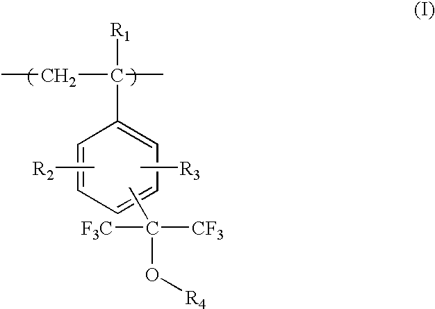
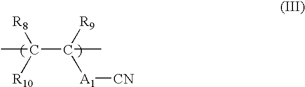
[0129]Into 60 ml 1-methoxy-2-propanol were dissolved 13.5 g (0.05 mol) of 4-[bis(trifluoromethyl)-hydroxymethyl] styrene and 3.4 g (0.05 mol) of methacrylonitrile. Further 0.25 g of 2,2′-azobis(2,4-dimethylvalelonitrile) (with a trade name V-65, made by Wako Pure Chemical Industries, Ltd.) was added as a polymerization initiator. The resulting solution was added dropwise over the period of 2 hours along with the injection of nitrogen gas into 10 ml of 1-methoxy-2-propanol kept at 70° C. After the completion of the addition, the mixture was agitated for additional 4 hours. The reaction mixture was poured into one liter of a mixture of methanol and ion-exchanged water (1 / 1) under vigorous stirring. The deposited resinous product was washed with ion-exchanged water, filtered and then dried under vacuum to give 14.8 g of a white resin. An NMR measurement confirmed that the product has a polymer structure represented by (I-1) / (III-2)=52 / 48 defined hereinabove, and a GPC measurement prove...

example 1

Measurement of Transmittance

[0132]As for Resins (1) to (6), a resist composition of the invention was prepared by dissolving 1.36 g of each resin, 0.02 g of the nonaflate salt of triphenylsulfonium (PAG4-3) and 0.02 g of an imidosulfonate compound (PAG6-19) in 8.5 g of propylene glycol monomethyl ether acetate, and then adding, to the solution, 0.005 g of dicyclohexylmethylamine and 0.01 g of Megafac R08 (made by Dainippon Ink and Chemicals, Inc.) as a fluorine-containing surfactant. As for Resins (7) to (12), a resist composition of the invention was prepared by dissolving 1.36 g of each resin, 0.04 g of the nonaflate salt of triphenylsulfonium (PAG4-3) and 0.02 g of an imidosulfonate compound (PAG6-19) in 8.5 g of propylene glycol monomethyl ether acetate, and then adding, to the solution, 0.005 g of dicyclohexylmethylamine and 0.01 g of Megafac R08 (made by Dainippon Ink and Chemicals, Inc.) as a fluorine-containing surfactant.

[0133]After filtered through a Teflon filter of 0.1 ...

example 2

Evaluation of Coating Performance and Development Defect

[0136]A series of resist compositions of the invention were prepared as in Example 1 except that the surfactant used in Example 1 was changed to one of the following W-1 to W-4. The surfactants used are shown in Table 5.

[0137]The surfactants used are as follows.

[0138]

TABLE 5SurfactantW1Megafac F176 (fluorine-containing, made by DainipponInk and Chemicals, Inc.)W2Megafac R08 (fluorine-containing andsilicon-containing, made by Dainippon Ink andChemicals, Inc.)W3Polysiloxane polymer KR-341 (made by Shin-EtsuChemical Co., Ltd.)W4Polyoxyethylene nonylphenyl ether

[0139]After filtered through a Teflon filter of 0.1 μm pore size, the solution of each sample was coated on a silicon wafer that had been treated with hexamethyl disilazane with use of a spin coater, and dried on a vacuum contact type-hot plate kept at 110° C. for 90 sec to give a 0.3 μm thick resist film. The coated film was subjected to an image exposure with a KrF excimer...


PUM

PropertyMeasurementUnit
Percent by massaaaaaaaaaa
Wavelengthaaaaaaaaaa

Abstract

A positive resist composition comprises: (A) a resin capable of decomposing by the action of an acid to increase the solubility in an alkali developer; and (B) a compound capable of generating an acid upon irradiation with one of an actinic ray and a radiation, wherein the resin (A) contains a specified repeating unit.

Description

FIELD OF THE INVENTION[0001]The present invention relates to a positive resist composition used in micro-lithographic processes for the manufacture of VLSI's and micro-tips with large capacities, and other photo-fabrication processes. More specifically, the invention relates to a positive resist composition capable of forming fine patterns with use of a vacuum ultraviolet ray having a wavelength of not longer than 160 nm.BACKGROUND OF THE INVENTION[0002]Integrated circuits are still raising the degree of integration; in the manufacture of semiconductor tips such as VLSI's, ultra-fine patterns comprising line widths of not more than a quarter micron must be processed. As one of the means to reduce the pattern dimensions, the use of an exposure energy source emitting a short wavelength radiation for the pattern formation is well known. The merit of shorter wavelength exposures can be understood by the Rayleigh's equation relating the resolution (line width) of an optical system to the...

Claims


Application Information

Patent Timeline
IPC IPC(8): G03F7/004G03F7/038G03F7/26G03F7/32G03F7/039
CPCG03F7/0046G03F7/0392G03F7/0397Y10S430/122Y10S430/108Y10S430/111G03F7/039
Inventor AOAI, TOSHIAKIMIZUTANI, KAZUYOSHIKANNA, SHINICHI
Owner FUJIFILM HLDG CORP
Why Eureka
Try Eureka