Gas-permeable membrane

a technology of gas-permeable membranes and coating polymers, which is applied in the direction of synthetic resin layered products, packaging, pipes, etc., can solve the problems of low otr and cotr values of continuous polymeric layers, and achieve the effects of controlling the variation of those characteristics, small thickness of coating polymers, and rough microporous films

Inactive Publication Date: 2007-01-30
LANDEC
View PDF109 Cites 35 Cited by
  • Summary
  • Abstract
  • Description
  • Claims
  • Application Information

AI Technical Summary

Benefits of technology

[0008]In describing the invention below, the following abbreviations, definitions, and methods of measurement are used. OTR is O2 permeability. COTR is CO2 permeability. OTR and COTR values are given in ml / m2.atm.24 hrs, with the equivalent in cc / 100 inch2.atm.24 hrs given in parentheses. OTR and COTR were measured using a permeability cell (supplied by Millipore) in which a mixture of O2, CO2 and helium is applied to the sample, using a pressure of 0.7 kg / cm2 (10 psi) except where otherwise noted, and the gases passing through the sample were analyzed for O2 and CO2 by a gas chromatograph. The cell could be placed in a water bath to control the temperature. The abbreviation P10 is used to denote the ratio of the oxygen permeability at a first temperature T1° C. to the oxygen permeability at a second temperature T2, where T2 is (T1-10)° C., T1 being 10° C. and T2 being 0° C. unless otherwise noted. The abbreviation R is used to denote the ratio of CO2 permeability to O2 permeability, both permeabilities being measured at 20° C. unless otherwise noted. Pore sizes given in this specification are measured by mercury porosimetry or an equivalent procedure. Parts and percentages are by weight, temperatures are in degrees Centigrade, and molecular weights are weight average molecular weights expressed in Daltons. For crystalline polymers, the abbreviation To is used to denote the onset of melting, the abbreviation Tp is used to denote the crystalline melting point, and the abbreviation ΔH is used to denote the heat of fusion. To, Tp and ΔH are measured by means of a differential scanning calorimeter (DSC) at a rate of 10° C. / minute and on the second heating cycle. To and Tp are measured in the conventional way well known to those skilled in the art. Thus Tp is the temperature at the peak of the DSC curve, and To is the temperature at the intersection of the baseline of the DSC peak and the onset line, the onset line being defined as the tangent to the steepest part of the DSC curve below Tp.
[0009]Typically, a microporous film has an R ratio of about 1, and OTR and COTR values which (i) are very high, (ii) do not change much with the thickness of the film, and (iii) do not change much with temperature (leading to P10 ratios of about 1). A continuous polymeric layer, on the other hand, typically has an R ratio substantially greater than 1 (generally 2 to 6, depending on the polymer itself), and has OTR and COTR values which (i) are relatively low, (ii) are inversely proportional to the thickness of the layer, and (iii) change substantially with temperature (leading to P10 ratios substantially greater than 1, generally at least 1.3). At practical thicknesses, such continuous polymeric layers have OTR and COTR values which are undesirably low.
[0010]We have discovered that when a membrane is prepared by coating a thin layer of a polymer onto a suitable microporous film, it has permeability characteristics which depend on both the coating polymer and the microporous film. We do not know exactly why this is so, and the results achieved by this invention do not depend upon any theory of its operation. However, we believe that the coating polymer effectively blocks most, but not all, of the pores of the microporous film (with the smaller pores being preferentially blocked); and that as a result, the permeability of the membrane results in part from gases which pass through the unblocked pores and in part from gases which pass through the coating polymer. In any event, the invention makes it possible to prepare novel membranes having very desirable permeability characteristics, and to achieve controlled variation of those characteristics. For example, the invention makes it possible to prepare membranes having an OTR greater than 775,000 (50,000), e.g. 1,550,000 (100,000) to 3,875,000 (250,000), or even higher, e.g. up to 7,750,000 (500,000) or more, a P10 ratio of at least 1.3, e.g. at least 2.6, and an R ratio of at least 1.5, e.g. at least 2.0.
[0011]The microporous film and the coating polymer must be selected and correlated to produce a membrane having particular properties, but those skilled in the art will have no difficulty, having regard to the disclosure in this specification and their own knowledge, in achieving a wide range of useful results.
[0012]The size and distribution of the pores in the microporous film are important factors. If the pores are too small, the coating polymer tends to form a continuous layer which is either too thin to be durable under routine handling, or too thick to have an acceptable OTR. If the pores are too large, the coating polymer may be unable to bridge over them, so that the coating polymer plays little or no part in determining the permeability characteristics of the membrane. This may happen even if the average pore size is relatively low, if the pores have a wide range of sizes; for example the coating polymer may effectively block many of the pores, but still fail to block the larger pores, whose permeability then dominates the permeability of the membrane as a whole.
[0013]The roughness of the microporous film can also be an important factor. The coating weight of the coating polymer must be very small, and in consequence the thickness of the coating polymer is also very small. If such a thin layer is in intimate contact with an irregular surface, it is more likely to be able to withstand abrasive forces during use than a layer of the same thickness which lies on a relatively smooth surface.

Problems solved by technology

At practical thicknesses, such continuous polymeric layers have OTR and COTR values which are undesirably low.
However, we believe that the coating polymer effectively blocks most, but not all, of the pores of the microporous film (with the smaller pores being preferentially blocked); and that as a result, the permeability of the membrane results in part from gases which pass through the unblocked pores and in part from gases which pass through the coating polymer.

Method used


Image

  • Gas-permeable membrane
  • Gas-permeable membrane
  • Gas-permeable membrane

Examples


examples

[0064]The invention is illustrated in the following Examples, a number of which are comparative Examples. In the Examples, the coating polymers used are often referred to by the following abbreviations.

[0065]SCC 1-15 and ACP. These acrylate polymers were prepared by polymerizing the monomers and parts by weight thereof shown in Table 1. In Table 1, the following abbreviations are used for the monomers. AA is acrylic acid, MAA is methacrylic acid, EHA is 2-ethylhexyl acrylate, C4A is butyl acrylate, C6A is hexyl acrylate, CY6MA is cyclohexylmethacrylate, C6DA is hexyldiacrylate, C12A is dodecyl acrylate, C12DA is dodecyl diacrylate, C14A is tetradecyl acrylate, C16A is hexadecyl acrylate, and C22A is behenyl acrylate. The monomers were copolymerized in a suitable solvent, e.g. toluene or a mixture of heptane and butyl acetate or ethyl acetate, using a suitable initiator, e.g. azobisisobutyronitrile (AIBN). For example, SCC11 was made by mixing the C6A and C14A with 0.31 parts of AIBN...

examples 1-10

and C1-4

[0071]Examples 1-10 and C1-4 are summarized in Tables 2-4 below. In each of the tests, the substrate identified in Table 2 was coated with a solution containing the identified percentage of the identified coating polymer. The coated substrate was dried, and its permeability to O2 and CO2 was measured at the temperature indicated in Table 2. The results are reported in Table 2. In some cases, the P10 ratios were calculated, as shown in Tables 3 and 4.

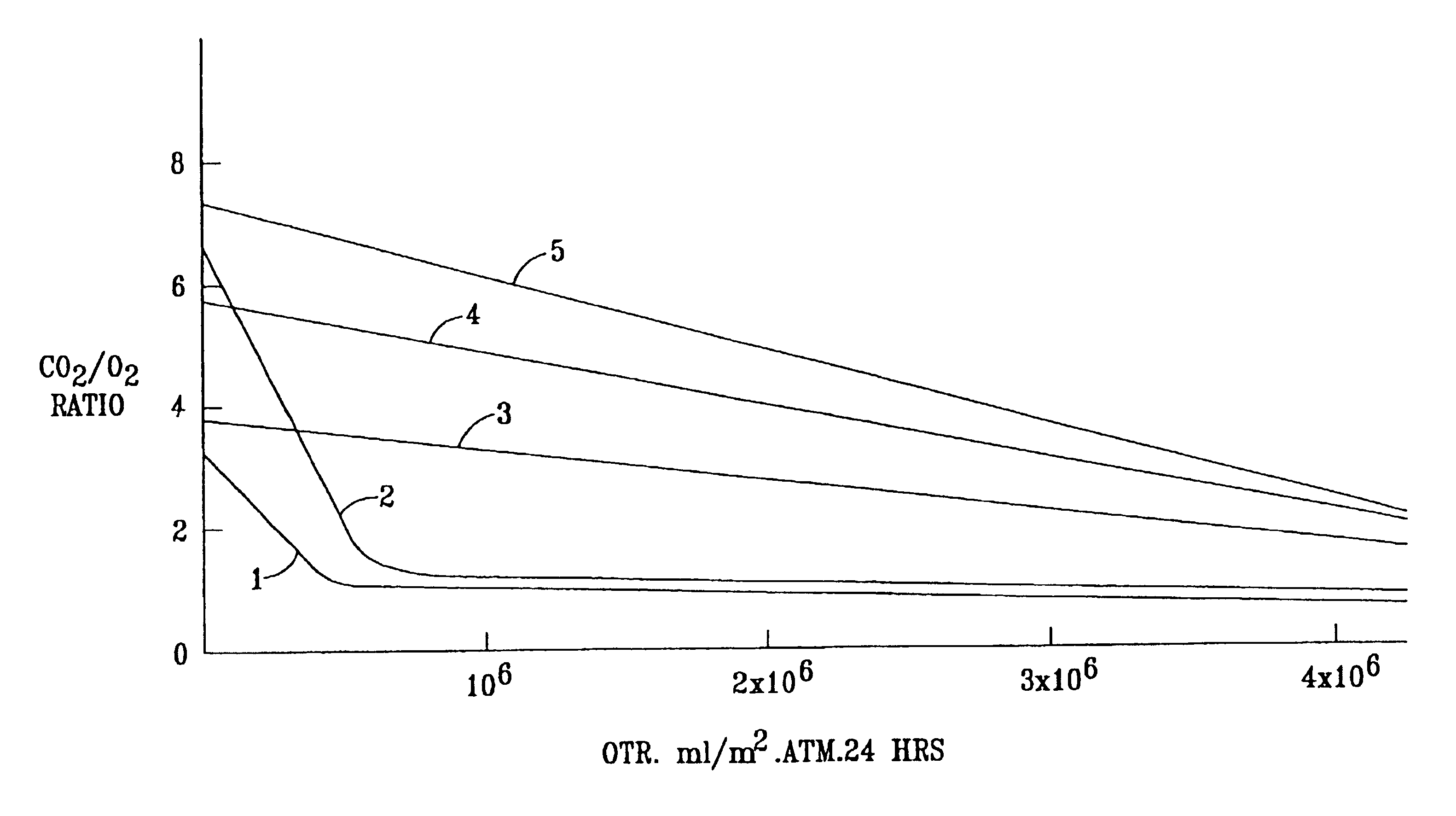
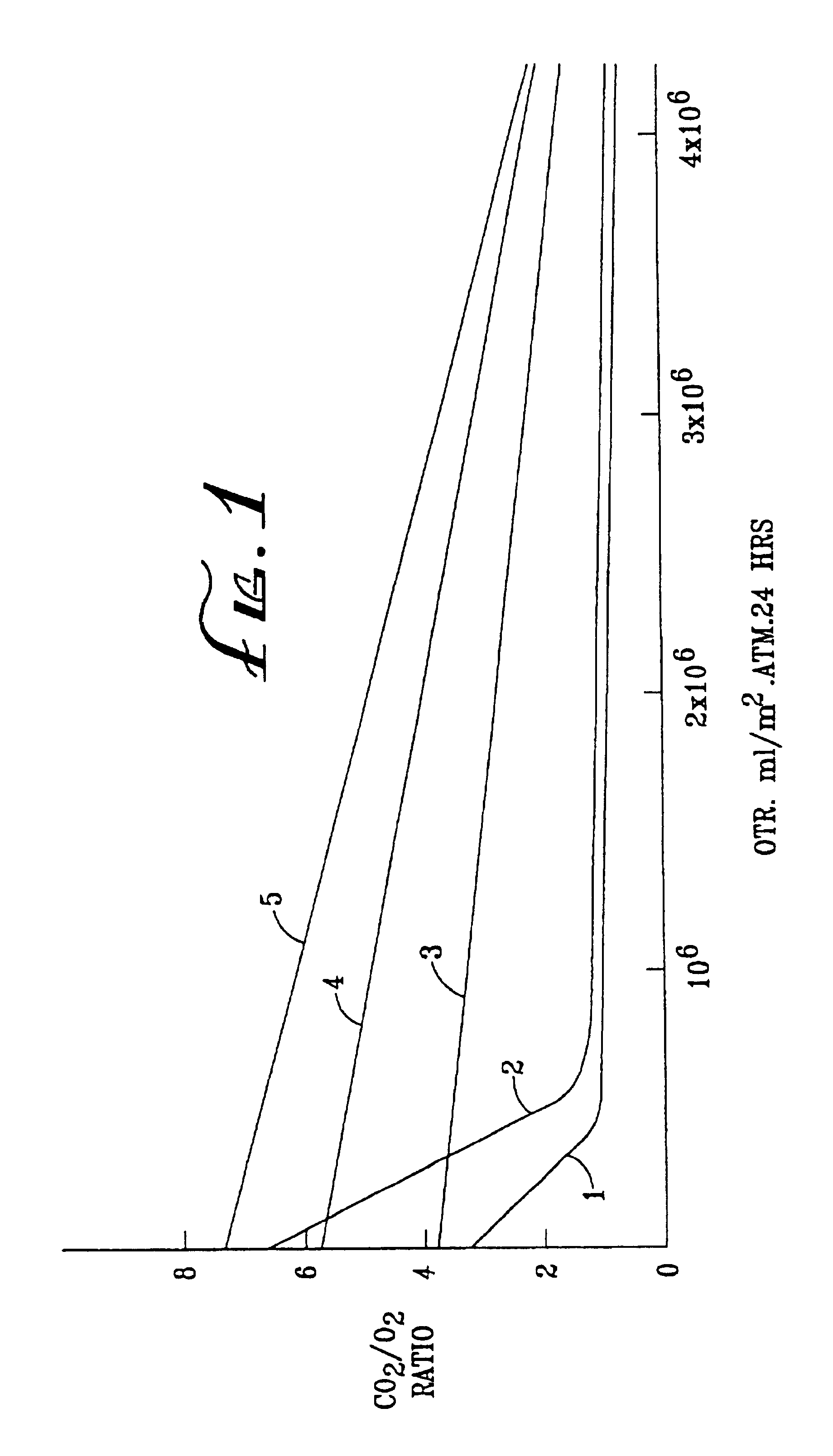
[0072]The OTR and R values of some of the Examples are shown graphically in FIG. 1 of the accompanying drawings. In FIG. 1, curve 1 represents comparative Examples 1K to 1N (SCC 1 on Van Leer), curve 2 represents comparative Examples 1H-J (SCC1 on MSX), curve 3 represents Examples 2O-Q (TPX on Teslin SP7), curve 4 represents Examples 1P, Q and R (SCC1 on Teslin SP7), and curve 5 represents Examples 2H to 2K (cis PB+SCC8 on Teslin SP7).

[0073]

TABLE 2 Coating PolymerPermeabilityEx No.SubstrateType%OTRRatio CO2 / O2° C.*1ACGSCC12**1.02...

example 11

[0076]A membrane was produced by coating SCC 10 at 8% concentration onto Teslin SP7. The resulting product was tacky to the touch. Second and third membranes were produced in the same way except that a crosslinking agent was added to the coating solution. The crosslinking agent was aluminum acetylacetonate (5%, based on polymer) or a polyfunctional aziridene (5%, based on polymer, available under the trade name XAMA 7 from Virginia Chemicals). The resulting products were much less tacky.


PUM


Abstract

Novel gas-permeable membranes which are particularly useful in the packaging of fresh cut fruit and vegetables, and other respiring biological materials. The membranes have an O2 permeability of at least 775,000 ml/m2.atm.24 hrs, a P10 ratio of at least 1.3, and a ratio of CO2 permeability to O2 permeability (R) of at least 1.5, and are made by forming thin polymeric coatings on microporous polymeric films. Preferred coating polymers are side chain crystalline polymers. Preferred microporous films contain inorganic fillers, particularly such films based on ultrahigh molecular weight polyethylene or polypropylene. FIG. 1 illustrates how O2 permeability and R ratio vary for different coating polymers and microporous films.

Description

CROSS-REFERENCE TO RELATED APPLICATIONS[0001]This application is a continuation of copending application Ser. No. 08 / 759,602, filed Dec. 5, 1996, by Raymond Clarke, Ray Stewart, Valentine Yoon, Donald Schultz and Bradley McClary. Ser. No. 08 / 759,602 is a continuation-in-part of application Ser. No. 08 / 453,018, filed May 30, 1995, by Raymond Clarke, Ray Stewart, Valentine Yoon, Donald Schultz and Bradley McClary, now abandoned. This application is also a continuation of International Application number PCT / U.S. 96 / 07939, filed May 29, 1996, by Landec Corp., naming Raymond Clarke, Ray Stewart, Valentine Yoon, Donald Schultz and Bradley McClary as inventors. The entire disclosure of each of Ser. Nos. 08 / 453,108 and 08 / 759,602 and PCT / U.S. 96 / 0939 is incorporated herein by reference for all purposes.BACKGROUND OF THE INVENTION[0002]1. Field of the Invention[0003]This invention relates to gas-permeable membranes and their use in packaging, especially the packaging of fresh produce.[0004]...

Claims


Application Information

Patent Timeline
Patent Type & Authority Patents(United States)
IPC IPC(8): B32B1/08C08J9/00B32B5/18B65D81/20B65D85/34C08J5/22C08J9/36C08L101/00C09D201/00
CPCB32B5/18B65D81/2069B65D85/34C08J5/2275C08J9/36B65D2565/388Y10T428/24322C08J2333/12Y10T428/259Y10T428/1334Y10T428/1352Y10T428/1321Y10T428/24998Y10T428/31663Y10T428/249978Y10T428/31928Y10T428/31935Y10T428/31855
Inventor CLARKE, RAYMONDSTEWART, RAY F.YOON, VALENTINE Y.SCHULTZ, DONALD A.MCCLARY, BRADLEY
Owner LANDEC
Why Eureka
Try Eureka