
Solar co-generator

a co-generationerator and solar energy technology, applied in the field of solar co-generationators, can solve the problems of inability to create re-absorption efficiency losses and heat loss of transfer fluids, and achieve the effects of improving conversion efficiency, improving energy conversion efficiency, and increasing photovoltaic efficiency

Inactive Publication Date: 2007-02-06
THE BOARD OF TRUSTEES OF THE UNIV OF ARKANSAS
View PDF33 Cites 40 Cited by
  • Summary
  • Abstract
  • Description
  • Claims
  • Application Information

AI Technical Summary

Benefits of technology

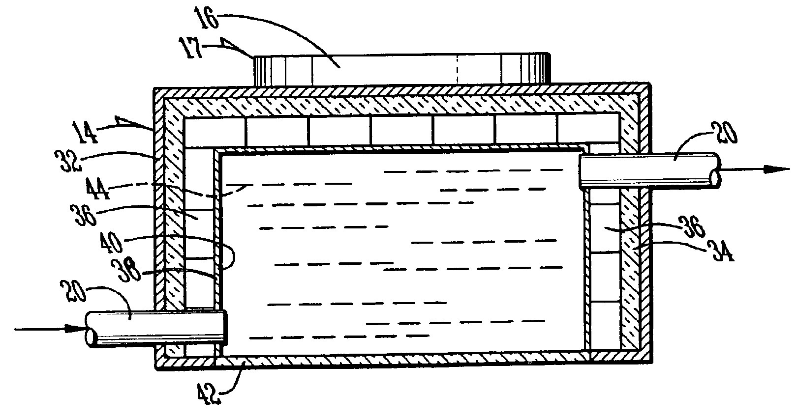
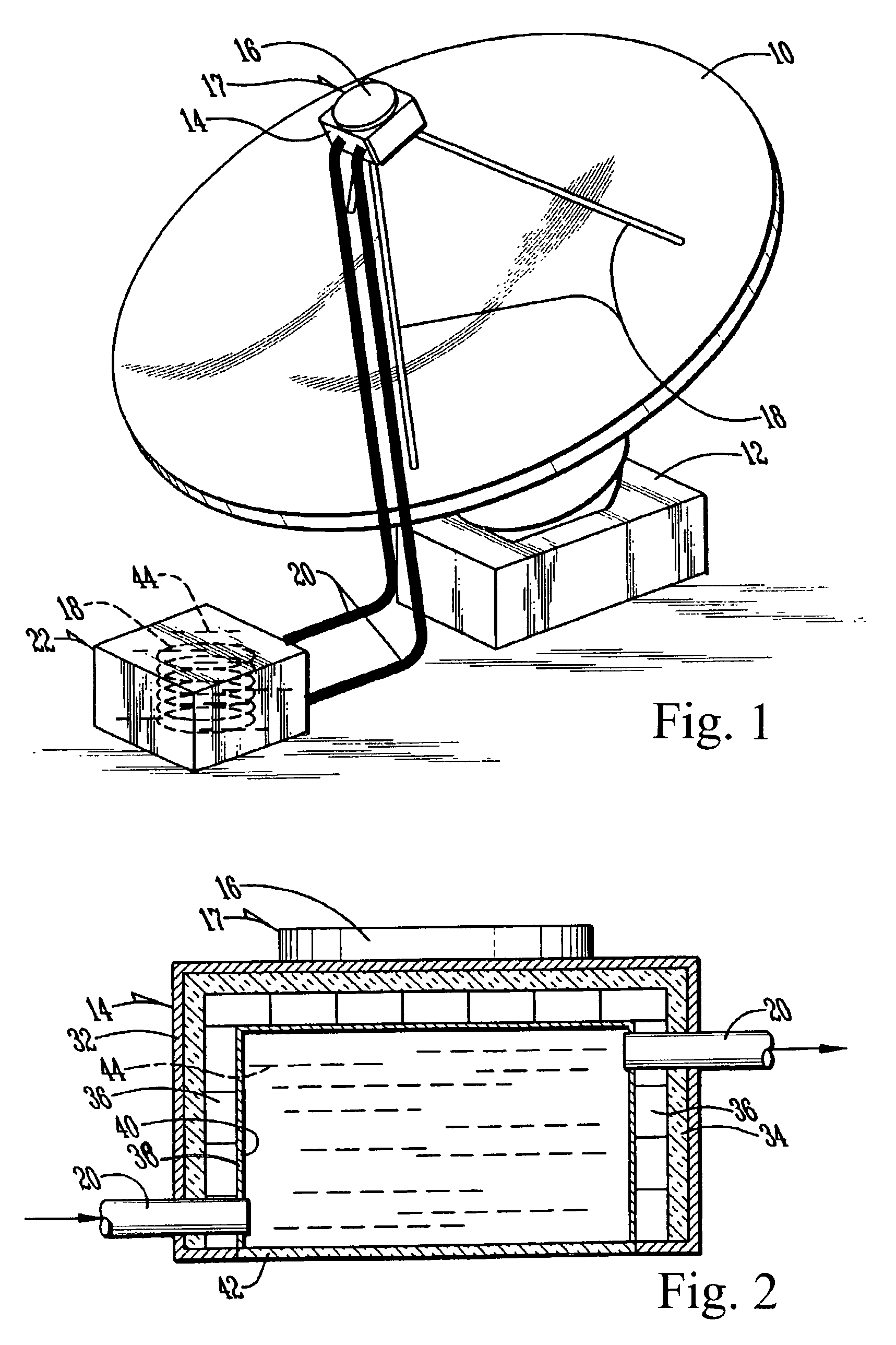
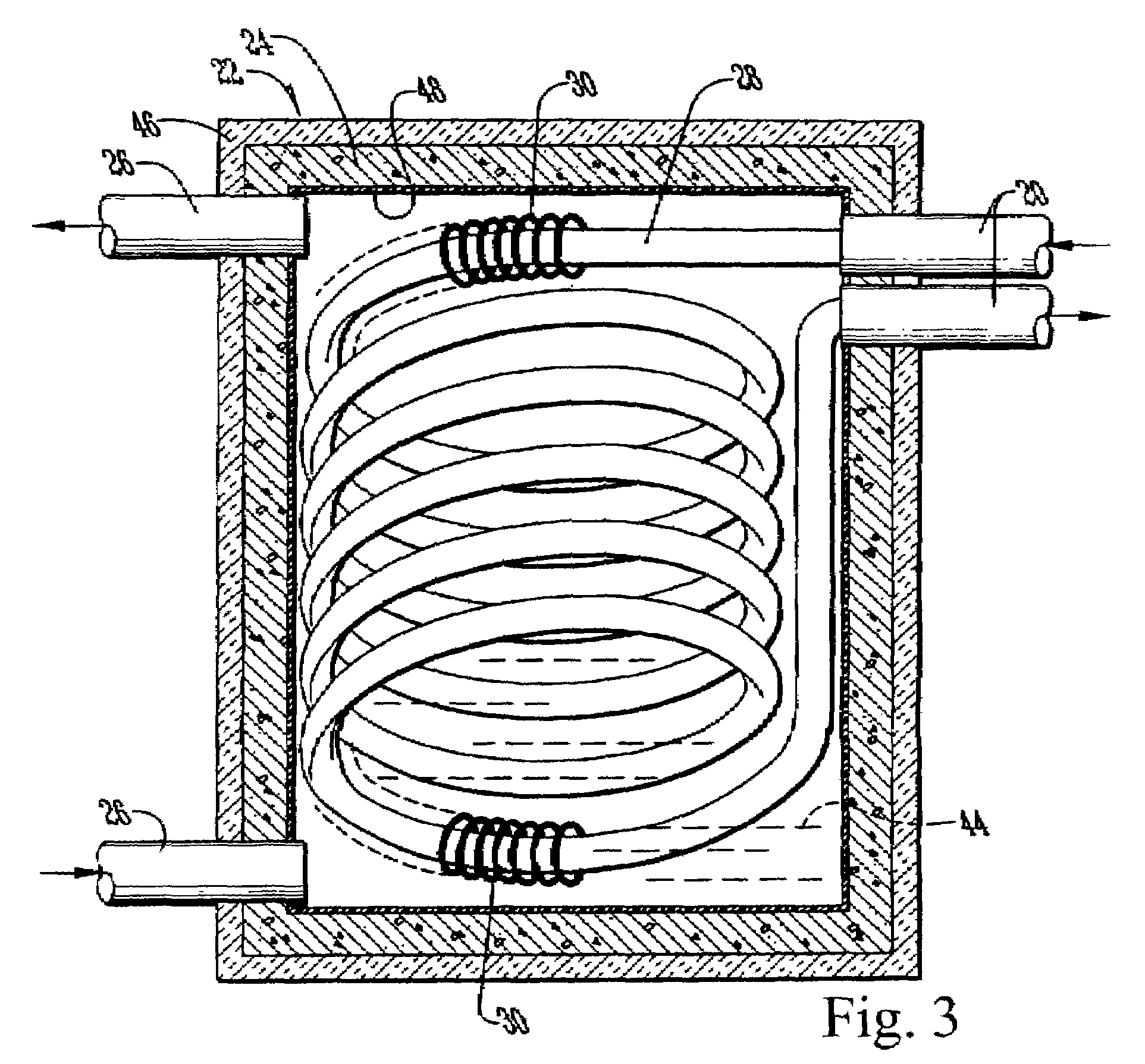
[0013]The present invention is directed to a co-generator system with improved energy conversion efficiency using a transfer fluid that acts to block longer-wavelength radiation from reaching the solar cells, thereby increasing photovoltaic efficiency, and also to diffuse the light incident upon the solar cells to further improve conversion efficiency. According to the present invention, a container houses a thermal transfer fluid that includes a suspension of an isotropic scattering agent and luminescent material. In certain preferred embodiments, the isotropic scattering agent is barium sulfate. A solar concentrator is used in certain embodiments to collect and concentrate light onto a window on the bottom of the container. Solar cells lining the container walls and back collect light passing from the concentrator, through the window, diffused in the transfer fluid, and finally isotropically scattered onto the solar cell surfaces. The particular thermal transfer fluid chosen is transparent to those radiation wavelengths within the solar cell operating range, but is opaque with respect to certain of the longer (infrared) wavelengths. Because the thermal transfer fluid is opaque with respect to these infrared frequencies, it prevents them from every reaching the solar cells. In this way, the solar cells are kept cooler than the solar cells in prior art systems that employ diffusion. Although the infrared radiation cannot penetrate through the container to the solar cells, it is absorbed by the transfer fluid. This results in a heating of the transfer fluid at a point removed from the solar cells. This heat is drawn away from the container and stored in a heat storage facility through the use of a pump and heat exchange system.
[0014]The present invention primarily uses barium sulfate or other isotropic scattering agents rather than a luminescent material as a medium for isotropic scattering of incident light. Because the scattering is direct, rather than indirect scattering through luminescent re-emission, the transfer fluid is less susceptible to degradation due to incident light. This is a particularly important advantage when a solar concentrator is employed as in certain embodiments of the present invention. Luminescent material is still used in the present invention for its property of absorbing shorter wavelength light that cannot be efficiently converted by solar cells, and re-emitting light in a band that is more usable by photovoltaic cells. In a preferred embodiment, this luminescent material is of an inorganic type that is less susceptible to degradation in any event. These materials also have the important advantage that they do not create the re-absorption problems experienced with organic dyes. Since materials such as barium sulfate simply scatter rather than absorb incident radiation, they cannot create re-absorption efficiency losses. The inorganic dyes described above absorb in the ultraviolet band only and emit in the green band only, thereby also avoiding any re-absorption problems.
[0015]Another feature of certain embodiments of the present invention is the application of an anti-reflective solar cell coating with fluorescent properties. Such a coating would increase the efficiency of a solar cell by evolving longer wavelengths from shorter incident wavelengths in the same manner as the luminescent materials described above. In the preferred embodiment, the fluorescing anti-reflective coating is formed using a thin film of ZnS:Cu, Al. The particular combination of scattering material, luminescent material, and a fluorescing anti-reflective coating results in a system with efficiency not reached by prior art devices using similarly efficient solar cells.
[0017]It is therefore an object of the present invention to provide for a solar co-generator of increased efficiency.
[0020]It is also an object of the present invention to provide a solar co-generator that utilizes a transfer fluid with luminescent material to increase the photovoltaic efficiency of the solar cells.
[0021]It is also an object of the present invention to provide a solar cell with a fluorescing anti-reflective coating to increase the efficiency of the cell.

Problems solved by technology

This results in a heating of the transfer fluid at a point removed from the solar cells.
Since materials such as barium sulfate simply scatter rather than absorb incident radiation, they cannot create re-absorption efficiency losses.

Method used


Image

  • Solar co-generator
  • Solar co-generator
  • Solar co-generator

Examples


Embodiment Construction

[0030]With reference to FIG. 1, a preferred embodiment of the present invention may be described. A solar concentrator 10 is mounted on tracking system 12 in a suitable location to receive sunlight. Solar concentrator 10 in the illustrated embodiment is of the parabolic dish type. The interior of solar concentrator 10 is coated with a reflective material, such as aluminum foil, or the concentrator 10 may itself be formed of a reflective material. Alternative shapes for solar concentrator 10 may include other three-dimensional (or point-type) systems, two-dimensional (or linear-type) systems, such as a Fresnel lens, or any of the various other concentrator types that are known in the art.

[0031]The embodiment is ideally placed in a location that has a direct line of sight to the sun during a significant portion of the day. Tracking system 12 makes it possible for concentrator 10 to follow the sun as it progresses across the sky during the day. Such tracking systems may take many diffe...


PUM


Abstract

A solar co-generator for producing both heat energy and electricity is disclosed. A solar concentrator directs sunlight into a container lined with solar cells and filled with a thermal transfer fluid. The fluid is transparent with respect to certain wavelengths of light that may be converted to electricity by the solar cell, but is opaque with respect to longer wavelengths, particular the infrared band. The infrared portion of the sunlight heats the thermal transfer fluid, which then transfer that heat through a storage facility using a heat exchange mechanism. The thermal transfer fluid increases the efficiency of photovoltaic generation by preventing heating of the solar cells due to infrared radiation. The thermal transfer fluid may be a mixture containing barium sulfate and a suspension of zinc sulfide phosphors. A fluorescing anti-reflective coating may be applied to the solar cells to further increase efficiency.

Description

BACKGROUND OF THE INVENTION[0001]The present invention relates to a generator that produces both heat and electricity from solar energy, and in particular to a solar energy co-generator that utilizes a transfer fluid to capture heat energy and increase the efficiency of photovoltaic generation.[0002]Solar energy is a renewable energy source with many well-known advantages over traditional fossil and nuclear energy resources. Solar energy has remained a largely untapped field, however, because the efficiency of existing solar power collection systems is generally too low to justify the required capital investment for these systems. While most of the electromagnetic radiation received from the sun falls in the visible spectrum (a wavelength range of approximately 430 to 690 nm), the sun's radiation also includes other components. In particular, solar energy incident upon the earth includes infrared radiation, a band that covers a wavelength range of approximately 1 μm to 1 mm. Typical...

Claims


Application Information

Patent Timeline
IPC IPC(8): H01L31/052H01L31/04H01L31/00
CPCF24J2/085H02S40/44F24J2/4649F24J2/5417F28D20/0034H01L31/052F24J2/12Y02E10/42Y02E10/43Y02E10/47Y02E10/52Y02E10/60Y02E60/142Y02E70/30Y10S136/291H02S40/425F24S23/71F24S80/20F24S20/20F24S30/45F24S23/31Y02E10/50Y02E60/14H01L31/055Y02E10/40
Inventor NICOLETTI, STEPHEN ADOLPHHAWK, ROGER M.
Owner THE BOARD OF TRUSTEES OF THE UNIV OF ARKANSAS
Learn More