Organic semiconductor material and organic electronic device

a technology of organic semiconductors and electronic devices, applied in the direction of organic chemistry, solid-state devices, thermoelectric devices, etc., can solve the problems of inadequate mobility and achieve the effects of excellent flexibility, light weight and scarce breakability

Inactive Publication Date: 2007-03-20
MITSUBISHI CHEM CORP
View PDF22 Cites 27 Cited by
  • Summary
  • Abstract
  • Description
  • Claims
  • Application Information

AI Technical Summary

Benefits of technology

[0115]As an example of an organic device of the present invention, a field effect transistor (FET) may be mentioned. This comprises two electrodes (a source electrode and a drain electrode) in contact with the semiconductor, and an electric current flowing between the electrodes (so-called a channel), is controlled by a voltage applied to another electrode so called a gate. The gate electrode is constructed merely to apply an electric field to the semiconductor layer, whereby an electric current will not basically flow, and it is called a field effect transistor.
[0116]According to the present invention, the organic semiconductor material is employed, and accordingly, it can be prepared by a process at a relatively low temperature, whereby a plastic film may be used as the substrate, and there is a merit in that a device which is light in weight, excellent in flexibility and scarcely breakable, can be prepared. Thus, it is possible to produce a field effect transistor having a thin film and being flexible, and such a transistor is used for a switching device for each cell, whereby an active matrix liquid crystal display having flexibility can be prepared, and thus it is widely applicable.
[0117]The operation characteristics of the field effect transistor are determined by e.g. the carrier mobility μ, the electroconductivity σ of the semiconductor layer, the capacitance Ci of the insulating layer, the structure of the device (the distance L and the width W between the source and drain electrodes, the thickness d of the insulating layer). As the semiconductor material to be used for the field effect transistor, the higher the carrier mobility μ, the better. However, the generalized porphyrin compound of the present invention has a characteristic that the carrier mobility μ is high, whereby when it is used for the field effect transistor, it is highly effective. Further, the field effect transistor of the present invention has a small leak current, and the ON / OFF ratio is large, whereby there is a merit that the stability of the film and the properties is high, and the useful life is long. Further, there are merits such that the useful temperature width is wide, the film forming property is good, it can be applicable to a large area, and it can be produced at low cost.
[0118]It is common to employ a structure wherein the gate electrode is insulated by an insulating film (Metal-Insulator-Semiconductor i.e. MIS structure). Further, there is a structure wherein a gate electrode is formed via a Schottkey barrier. However, in the case of FET employing an organic semiconductor material, the MIS structure is commonly employed.
[0119]Now, the field effect transistor of the present invention will be described in further detail with reference to the drawings, but the present invention is by no means restricted to such structures.
[0120]In FIGS. 1A to 1D, some structural examples of the field effect transistor device are shown. Reference numeral 1 represents a semiconductor layer, 2 an insulator layer, 3 and 4 a source electrode and a drain electrode, 5 a gate electrode, and 6 a substrate. The disposition of the respective layers and electrodes can be suitably selected depending upon the application of the device. As the electric current flows in a direction parallel to the substrate, the device is called a horizontal FET.

Problems solved by technology

However, in that application, the mobility has been still inadequate, probably because purification of the porphyrin itself has been inadequate.
Thus, heretofore, no attention has been drawn to a porphyrin compound as a material for an organic electronic device, since its synthesis or purification has been difficult.

Method used


Image

  • Organic semiconductor material and organic electronic device
  • Organic semiconductor material and organic electronic device
  • Organic semiconductor material and organic electronic device

Examples


preparation example 2

[0199]0.02 g of the bicyclo compound (1) of Preparation Example 1 and 0.1 g of zinc acetate dihydrate were put in a solvent mixture comprising 30 ml of chloroform and 3 ml of methanol, followed by stirring at room temperature for 3 hours. The reaction solution was washed twice with 100 ml of water and once with 40 ml of a saturated sodium chloride aqueous solution. The organic phase was dried over sodium sulfate. The solvent was distilled off, and the obtained solid was recrystallized from a solvent mixture of chloroform and methanol to obtain 0.022 g of a zinc complex of the bicyclo compound (1). Further, by gel permeation chromatography (Nippon Bunseki Kogyo JAIGEL-1H, 2H, chloroform), only the single peak was fractionated and purified.

[0200]The mass spectrum was measured, and the molecular peak was confirmed.

PREPRATION EXAMPLE 3

Preparation of 21,23-dithiaporphyrin 5

[0201]A dithiaporphyrin compound having the following bicyclo ring structure was prepared by the following synthesis...

preparation example 4

Preparation of 21-thiaporphyrin

[0212]In the same manner as in Preparation Example 3, thiatripyran dicarboxylic acid 4 was prepared. In the same manner as in Preparation Example 3 except that this thiatripyran dicarboxylic acid 4 and a pyrrole derivative instead of thiophene were employed, a thiaporphyrin compound having the following bicyclo structure was prepared by the following synthesis route.

[0213]

[0214]Into a light-shielded 500 ml flask, thiatripyran dicarboxylic acid 4 (0.508 g, 0.9 mmol) was put, and after flushing the interior with argon, 2.5 ml of TFA was put at room temperature, followed by stirring for 5 minutes. 200 ml of dry CH2Cl2 was added, and then, diformylpyrrole (0.181 g, 0.9 mmol) was quickly added, followed by stirring at room temperature for 16 hours. Then, triethylamine was slowly added to neutralize the solution, and then DDQ (0.227 g, 1.0 mmol) was added, followed by stirring for further 2 hours. The obtained solution was washed with water, a saturated sodi...

example 1

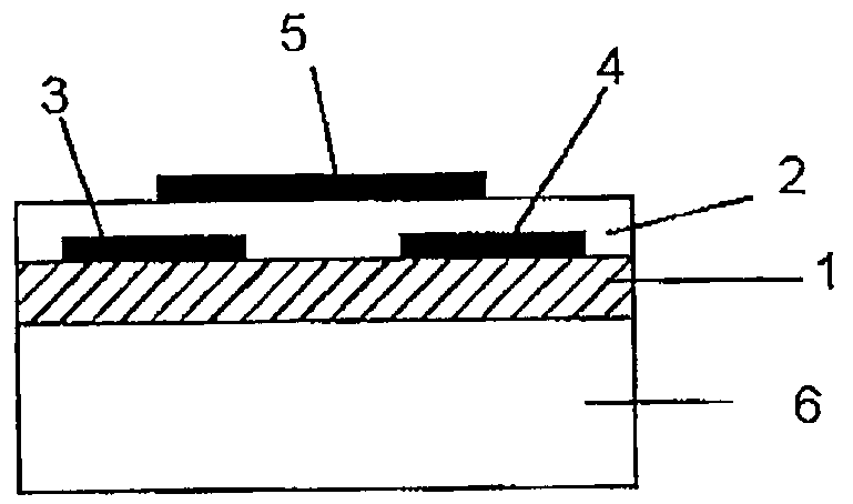
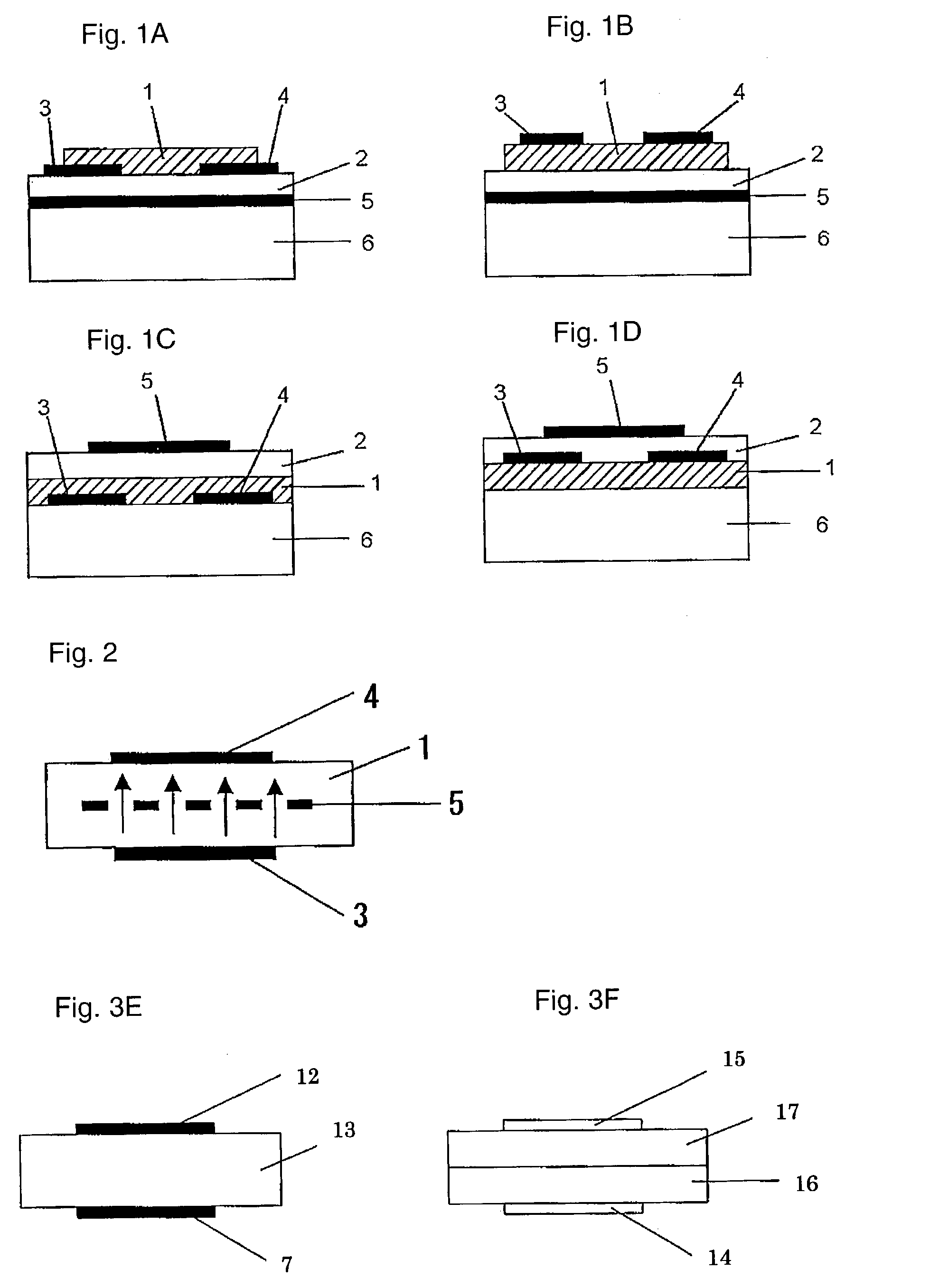
[0215]On a N-type silicon substrate (Sb-doped, resistivity: at most 0.02 Ωcm, manufactured by Sumitomo Metals Industries, Ltd.) having 300 nm of an oxide film formed thereon, gold electrodes (source and drain electrodes) having a length (L) of from 2.5 to 50 μm, a width (W) of 250 μm or a gap of 1,000 μm, were formed by photolithography. Further, the oxide film at a position different from these electrodes, was etched with a hydrofluoric acid / ammonium fluoride solution, and to the exposed Si portion, gold was vapor-deposited to form an electrode (gate electrode) to apply a voltage to the silicon substrate.

[0216]2 mg of the bicyclo compound (1) obtained in Preparation Example 1 was dissolved in 1 ml of chloroform, and this solution was dropped between the source and drain electrodes, followed by evaporation of the solvent, and this operation was repeated a few times to obtain a good film. The X-ray diffraction of this film was observed, whereby no sharp peak was observed. Further, th...


PUM

PropertyMeasurementUnit
temperatureaaaaaaaaaa
ionization potentialaaaaaaaaaa

Abstract

An organic semiconductor material comprising a compound which has a generalized porphyrin skeleton and which has a molecular structure such that the distance from the generalized porphyrin ring plane to the center of each atom forming the generalized porphyrin skeleton, is not more than 1 Å.

Description

[0001]The entire disclosures of Japanese Patent Application No. 2002-089425 filed on Mar. 27, 2002, Japanese Patent Application No. 2002-104639 filed on Apr. 8, 2002 and Japanese Patent Application No. 2003-049561 filed on Feb. 26, 2003 including specifications, claims, drawings and summaries are incorporated herein by reference in their entireties.BACKGROUND OF THE INVENTION[0002]1. Field of the Invention[0003]The present invention relates to an organic semiconductor material and an organic electronic device such as a field effect transistor. Particularly, it relates to an organic semiconductor material comprising a generalized porphyrin compound having a specific structure, and an organic electronic device employing such a material.[0004]2. Discussion of the Background[0005]Heretofore, as a field effect transistor (hereinafter sometimes referred to as FET) device, one employing, as a semiconductor layer, an inorganic semiconductor material such as a silicon (Si) or gallium arsenid...

Claims


Application Information

Patent Timeline
Patent Type & Authority Patents(United States)
IPC IPC(8): H01L35/24C07D487/22C07D513/22C07D519/00H01L51/05H01L51/30
CPCC07D487/22C07D513/22C07D519/00H01L51/0067H01L51/0073H01L51/0074H01L51/0077H01L51/0092H01L51/0072H01L51/0052H01L51/0545H10K85/615H10K85/30H10K85/381H10K85/654H10K85/6576H10K85/6574H10K85/6572H10K10/466
Inventor ARAMAKI, SHINJIONO, NOBORU
Owner MITSUBISHI CHEM CORP
Why Eureka
Try Eureka