High surface area substrates for microarrays and methods to make same

a technology of high surface area and substrate, applied in the field of organic chemistry, biochemistry, molecular biology, etc., can solve the problems of limited access to biomolecules in optimal systems, difficult to achieve with conventional devices, and substantial restrictions on dispensing equipment, so as to improve the uniformity of signal intensity, improve analytical accuracy, and improve the effect of accuracy

Inactive Publication Date: 2007-03-27
BIOMICROARRAYS +1
View PDF42 Cites 173 Cited by
  • Summary
  • Abstract
  • Description
  • Claims
  • Application Information

AI Technical Summary

Benefits of technology

[0024]In another embodiment of the substrate, at least one spatially discrete region comprises a well, said well comprising at least two microfeatures and a plurality of microstructures that are each integral to the bottom of the well, said microstructures are smaller in dimension than each of the microfeatures. Each of the plurality of microfeatures may be smaller in dimension than an array element of the microarray, said array element comprises a textured array element comprised of at least two microfeatures. The textured array element may provide local replications of measurements as compared to a non-textured array element. Each of the local measurements in said textured array element may be of uniform intensity as compared to a non-textured array element. At least one of the microfeatures of the textured array element may function as a well-defined boundary of said textured array element.
[0028]In yet another embodiment of the invention, there is a microarray having improved analytical accuracy comprising a high surface area substrate, the substrate comprising a plurality of microfeatures on a surface of the substrate arranged in spatially discrete regions to produce a texture on the surface, wherein the textured surface provides an improvement in accuracy as compared to a non-textured surface. Each of the plurality of microfeatures may be smaller in dimension than an array element of the microarray, the array element comprises a textured array element comprised of at least two microfeatures. The textured array element may provide local replications of measurements. At least one of the microfeatures of the textured array element functions as a well-defined boundary of said textured array element.
[0029]In another embodiment of the present invention, there is a microarray having improved uniformity of signal intensity comprising a high surface area substrate, the substrate comprising a plurality of microfeatures on a surface of the substrate arranged in spatially discrete regions to produce a texture on the surface, wherein the textured surface provides the improvement in the uniformity of the signal intensity as compared to a non-textured surface. Each of the plurality of microfeatures may be smaller in dimension than an array element of the microarray, said array element comprises a textured array element comprised of at least two microfeatures.

Problems solved by technology

Further, it was suggested that the drop of the solution is deposited in such a manner as to synchronize spatially with each of the hydrophilic array elements, however, requiring alignment imposes a substantial restriction on the dispensing equipment, which, in many cases, is difficult to attain with conventional devices.
However, accessiblity of biomolecules in the optimal systems was not maximized, i.e., the means for molecules to penetrate the pores is difficult and kinetically challenging with respect to achieving sufficient proximity to a specific binding site.
Further, in the wash step, this problem manifests itself because non-specific molecules get physically trapped within the pores.
In describing suitable inorganic materials for providing the pores within the top surface of the substrate, it was observed that sol-gel coating and Vycor provided relatively poor accessibility of the polynucleotide (i.e., DNA) for hybridization.
The porous coatings described in the prior art resulted in at least one of several problems such as inadvertent trapping of the targets (and probes), poor access of longer and / or larger molecules to the pores and long hybridization times. The inadvertent trapping of the molecules result in the background signal to rise and thus negate the advances made in the increased signal.
However, the construction introduces many constraints in the chip design, and the analysis requires special equipment, thereby adding to the cost.
Otherwise, the structural increase in surface area does not fully translate into a microarray device having increased surface area.

Method used


Image

  • High surface area substrates for microarrays and methods to make same
  • High surface area substrates for microarrays and methods to make same
  • High surface area substrates for microarrays and methods to make same

Examples


example 1

Substrate Having an Accessible Microfeature

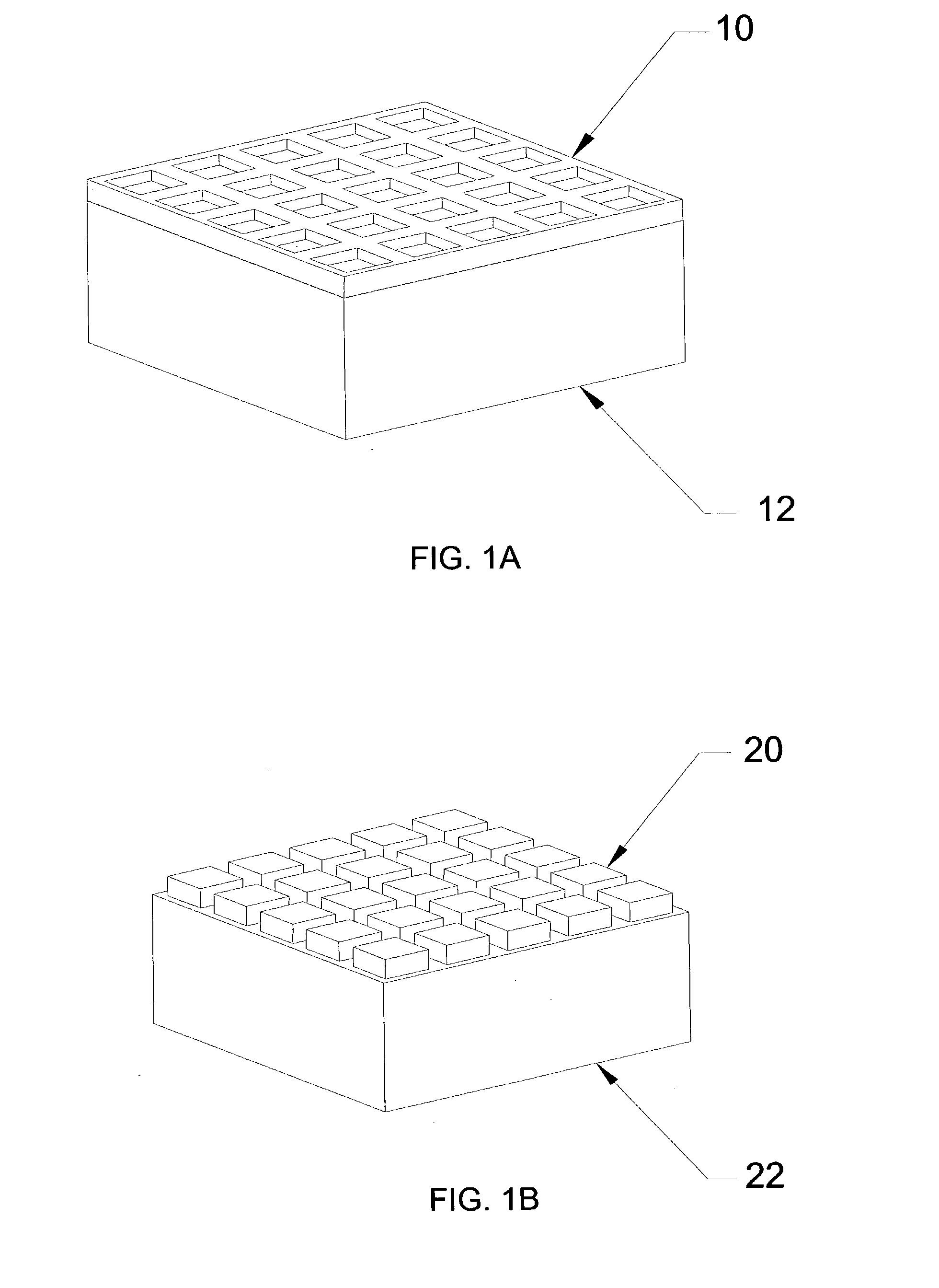
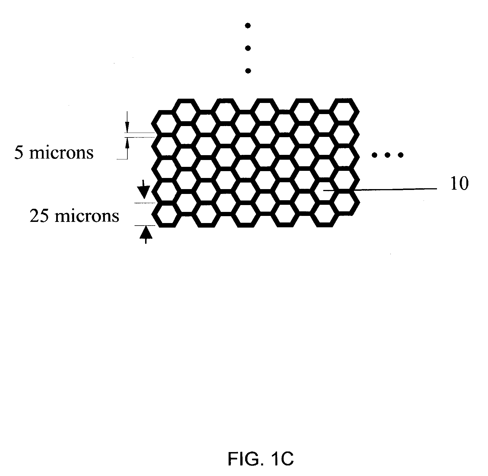
[0209]A sodalime silicate glass substrate B270 from Schott Glass (Yonkers, N.Y.) was cleaned and coated by evaporation with a 200 nanometer layer of chromium. The chromium layer was patterned using photolithographic methods to form a series of 7 mm diameter areas comprising nested structural elements, as illustrated in FIGS. 11A to 11C. Each area was patterned differently with respect to the size, shape, and / or density of microfeatures and / or microstructures that were generated in the area.

[0210]The chromium covered patterned substrate was acid etched by immersing in a 6 weight % hydrofluoric acid solution for 30 seconds and rinsed immediately with deionized water. The etch rate was 0.017 microns / second. The chromium was removed from the surface by placing the substrate in a hydrochloric acid (37 weight %) solution at 60° C. with the addition of a small chunk (˜0.2 g) of aluminum as a catalyst. Analysis of the cleaned etched glass substrate...

example 2

Higher Surface Area Afforded by Substrate Comprising Microfeatures

[0212]The silanization process was performed on a textured surface of the substrates made in Example 1. After cleaning, the slides were immediately immersed in deionized H2O to prevent NaOH crystallization. The slides were then rinsed in ethanol and placed in a 50° C. oven to dry. A 1% (v / v) solution of 3-glycidoxypropyltrimethoxysilane in toluene was prepared in a glass vessel into which the slides were immersed for 16 hours. After silanization, the slides were rinsed with toluene and allowed to dry in a 50° C. oven. They were stored under vacuum in a desiccator until use.

[0213]The probe was applied in a 1 / 100 ratio of 5′-Cy3-3′ amine oligonucleotide / ′5 unlabeled-3′ amine olignucleotide onto each feature in 1 μl spots at two final probe concentrations, 25 and 50 μM. Control spots were also placed onto the non-etched area of the slides (i.e., outside of the etched well) and on the non-etched control slides. The slides...

example 3

Generating a Microfeature using a Photoresist

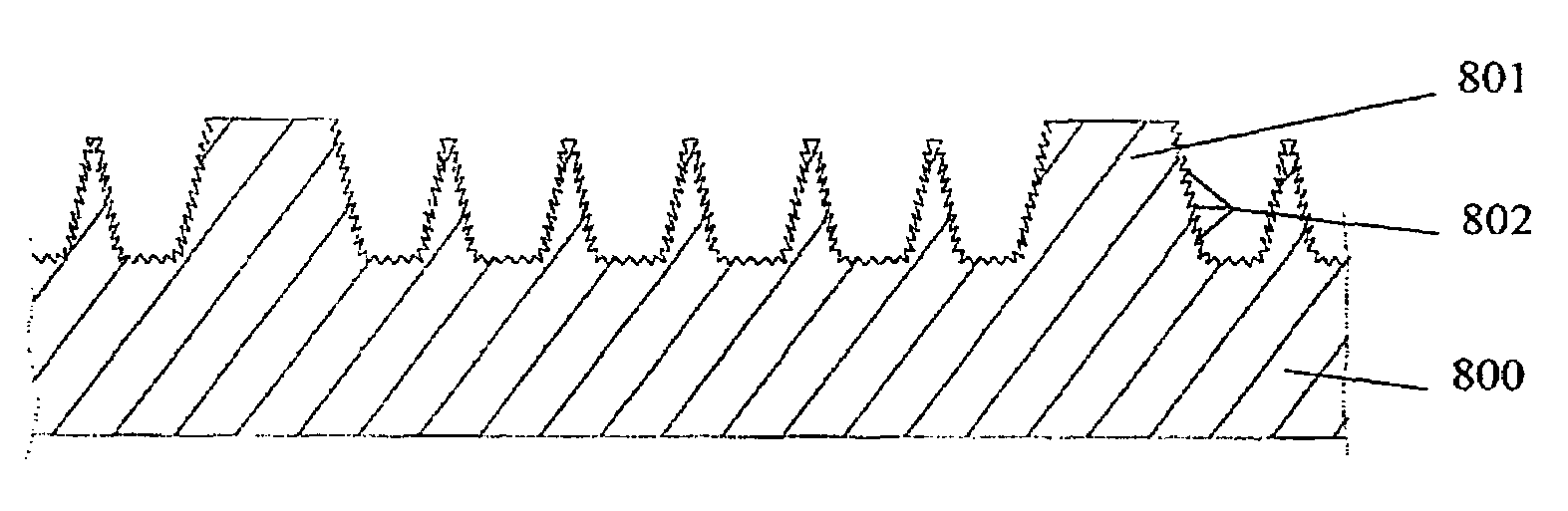
[0215]The substrates of the present invention comprise microfeatures, and the microfeatures were formed using a photoresist coating. The photoresist layer was deposited on the surface of the substrate and was patterned. The resulting walls of the residual photoresist (in the unexposed areas) increased the surface area of the substrate. A flexible photoresist having a wall height in the range of about 2 to about 100 microns is preferably used to generate a microfeature. For example, the Shin-etsu MicroSi (Phoenix, Ariz.) photoresist SINR-3170M series (e.g. SINR-3170M-13) is processed by first uniformly coating a substrate by spin coating. The substrate is cleaned prior to the coating step. The coating parameters are adjusted to control the thickness, and the coated substrate is heated to about 100° C. for 2 minutes. The coated substrate is exposed, using a contact method or a non-contact method, through a patterned mask to an appropriate r...


PUM

PropertyMeasurementUnit
diameteraaaaaaaaaa
volumeaaaaaaaaaa
volumeaaaaaaaaaa

Abstract

The present invention is directed to a substrate having a plurality of microfeatures that provide a high surface area and are open to provide ready access to fluids and components therein. Methods of making the high surface area substrates are described and include generating microfeatures and / or microstructures on the surface of the substrate.

Description

CROSS-REFERENCE TO RELATED APPLICATIONS[0001]This application claims benefit of and priority to U.S. provisional patent applications, Ser. No. 60 / 345,848, filed Nov. 9, 2001, Ser. No. 60 / 361,588, filed Mar. 2, 2002, and Ser. No. 60 / 393,044, filed Jul. 1, 2002.TECHNICAL FIELD[0002]The present invention relates to the fields of inorganic chemistry, organic chemistry, molecular biology, biochemistry and medicine. The invention is directed to methods of preparing substrates, having a high surface area for use as a microarray device, that involve forming structural microfeatures on a surface of the substrate that increase surface area and accessibility thereto. Further, the textured surface further comprises microstructures and / or physical surface features, such as pits, that further contribute to the increased surface area. Compositions directed to the substrates of the invention are also described.BACKGROUND OF THE INVENTION[0003]A rapid explosion in the sequencing of entire genomes ha...

Claims


Application Information

Patent Timeline
Patent Type & Authority Patents(United States)
IPC IPC(8): C12Q1/68B01J19/00B01L3/00B81B1/00B81B3/00
CPCB01J19/0046B81C1/00206B01L3/5085B01L3/5088B81B1/006B01J2219/00378B01J2219/00387B01J2219/00504B01J2219/00527B01J2219/00574B01J2219/00576B01J2219/00585B01J2219/00596B01J2219/00605B01J2219/0061B01J2219/00612B01J2219/00617B01J2219/00621B01J2219/00628B01J2219/00635B01J2219/00637B01J2219/00644B01J2219/00659B01J2219/00677B01J2219/00722B01J2219/00725B01J2219/00734B01J2219/00743B01L2200/12B01L2300/0819B01L2300/16B01L2300/166B81B2201/0214B01J2219/00317
Inventor AGRAWAL, ANOOPCRONIN, JOHN P.TONAZZI, JUAN C.GOODYEAR, A. G.LECOMPTE, ROBERT S.HOGAN, MICHAEL E.GALBRAITH, DAVID W.
Owner BIOMICROARRAYS
Why Eureka
Try Eureka