Anode for secondary battery, secondary battery using same and method for fabricating anode

a secondary battery and anode technology, applied in the field of secondary batteries and secondary batteries, can solve the problems of reducing the battery life, shortening the charge-discharge cycle life, and shortening the cycle life of the battery, and achieve excellent cycle performance and high energy density

Inactive Publication Date: 2007-04-10
NEC CORP
View PDF18 Cites 65 Cited by
  • Summary
  • Abstract
  • Description
  • Claims
  • Application Information

AI Technical Summary

Benefits of technology

[0030]As described, the multi-layered structure is employed in the present invention which includes a first anode layer (the first layer) having the carbon as the main component, a second anode layer (the second layer) made of the film-like material through which the lithium component passes; and a third anode layer (the third layer) containing the lithium and / or the lithium-containing compound as a main component. In the battery including this anode and a cathode capable of inserting and extracting lithium ions, the higher charge-discharge efficiency and discharge capacity are compatible because the Li in the third anode layer in the anode efficiently compensates the irreversible capacity of the anode. Part of the Li in the third anode layer is doped into the second anode layer (the second layer) to improve the permeability of the lithium component in the second anode layer (the second layer). The uniform existence of the film-like material having such higher permeability of the lithium component in the anode makes uniform the electric field distribution between the cathode and the anode. As a result, the excellent cycle performance can be realized by preventing the local concentration of the electric field.
[0031]Further, in accordance with the battery using the anode of the present invention, because the structure of the anode includes the lithium alloy having the excessive lithium with respect to the theoretical composition at the fully charged condition, the excellent cycle performance can be obtained by suppressing the generation of dendrite and the reaction with the other layers such as the carbon-containing layer.
[0032]If a metal selected from Si, Ge, Ag, Sn, In and Pb is contained in the second layer made of the film-like material having the lithium ion conductivity and the second layer is an amorphous structure, the battery capacity can be increased while maintaining the higher operating voltage and the higher charge-discharge efficiency.
[0034]The battery having the higher energy density and the excellent cycle performance can be obtained by adjusting the ratio of the reversible capacity of the anode with respect to that of the cathode in a range from 1.0 to 1.3 in the present invention.

Problems solved by technology

However, in this case, with the progress of the cycles of the charging and the discharging, needle crystals (dendrite) deposited on the lithium surface during the charging penetrate a separator to cause the internal short-circuit failure, thereby reducing the battery life.
The pulverization causes a problem of the shorter charge-discharge cycle life.
If a carbon material such as graphite and hard carbon which is capable of inserting and extracting the lithium ion is used as the anode, a problem arises, though the charge-discharge cycles can be excellently repeated, that the energy density is lower because the capacity of the graphite material is lower than the metal lithium or the lithium alloy and the irreversible capacity of the hard carbon at the initial charging and discharging is large to make the charge-discharge efficiency lower.
However, the technique in which small-sized aluminum is added to a carbon material disclosed in JP-A-9(1997)-259868 arises problems such that the charge-discharge condition of an electrode is made non-uniform, and the deformation of the electrode and the peeling-off of an active material from a current collector are generated due to the local concentration of an electric field after the repetition of charge-discharge cycles because the uniform dispersion of the metal particles in the carbon material is difficult and the metal is localized in the anode.
Accordingly, the cycle performance can be hardly maintained at a higher level.
An SnBbPcOd (“b” is 0.4 to 0.6, “c” is 0.6 to 0.4 and “d” is 1 to 7) metal oxide amorphous material disclosed in WO96 / 33519 has a problem that the energy density of a battery can be hardly increased to a sufficient level because the irreversible capacity after an initial charge-discharge is larger.
Further, the above prior arts have a common problem that a higher operating voltage cannot be obtained.
Accordingly, the lower operating voltage narrows the usable region, and consequently the capacity increase in the region where the battery is actually used can be hardly attained.
On the other hand, the anode material containing aluminum and disclosed in JP-A-5(1993)-234583 has a problem of the rapid capacity decrease after the repetition of cycles.
The lithium contained in such a film is electrochemically inactive and cannot contribute to the increase of the charge-discharge capacity of the battery.
Accordingly, the above methods cannot sufficiently improve the charge-discharge efficiency.
Further, the larger electric resistances of these films increase the resistance of the battery to decrease the effective capacity of the battery.
The non-uniformity of the metal distribution can be microscopically inevitable in the above sheet, thereby generating the local concentration of the electric field.
Due to the above reasons, the cycle performance can be hardly maintained at a higher level.
Since the irreversible capacity part of the anode is at first compensated with the lithium component of the reversible capacity part of the cathode and then the reversible capacity part of the anode is charged, the energy efficiency of the secondary battery including the cathode and the anode having the capacities shown in FIG. 1b is not guaranteed to increase, and is likely to decrease.

Method used


Image

  • Anode for secondary battery, secondary battery using same and method for fabricating anode
  • Anode for secondary battery, secondary battery using same and method for fabricating anode
  • Anode for secondary battery, secondary battery using same and method for fabricating anode

Examples


example 1

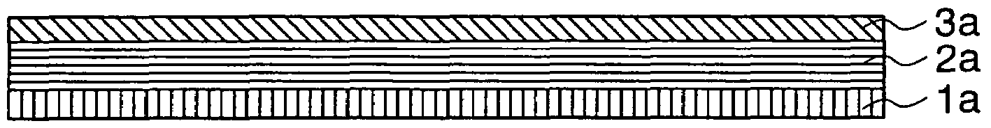
[0108]In the present Example, a copper foil and graphite were used as a current collector 1a and the main component of a carbon anode layer 2a, respectively. A second anode layer 3a made of B2O3 was formed by using a vacuum-evaporation method. A third anode layer 4a made of metal lithium was formed by using a vacuum-evaporation method.

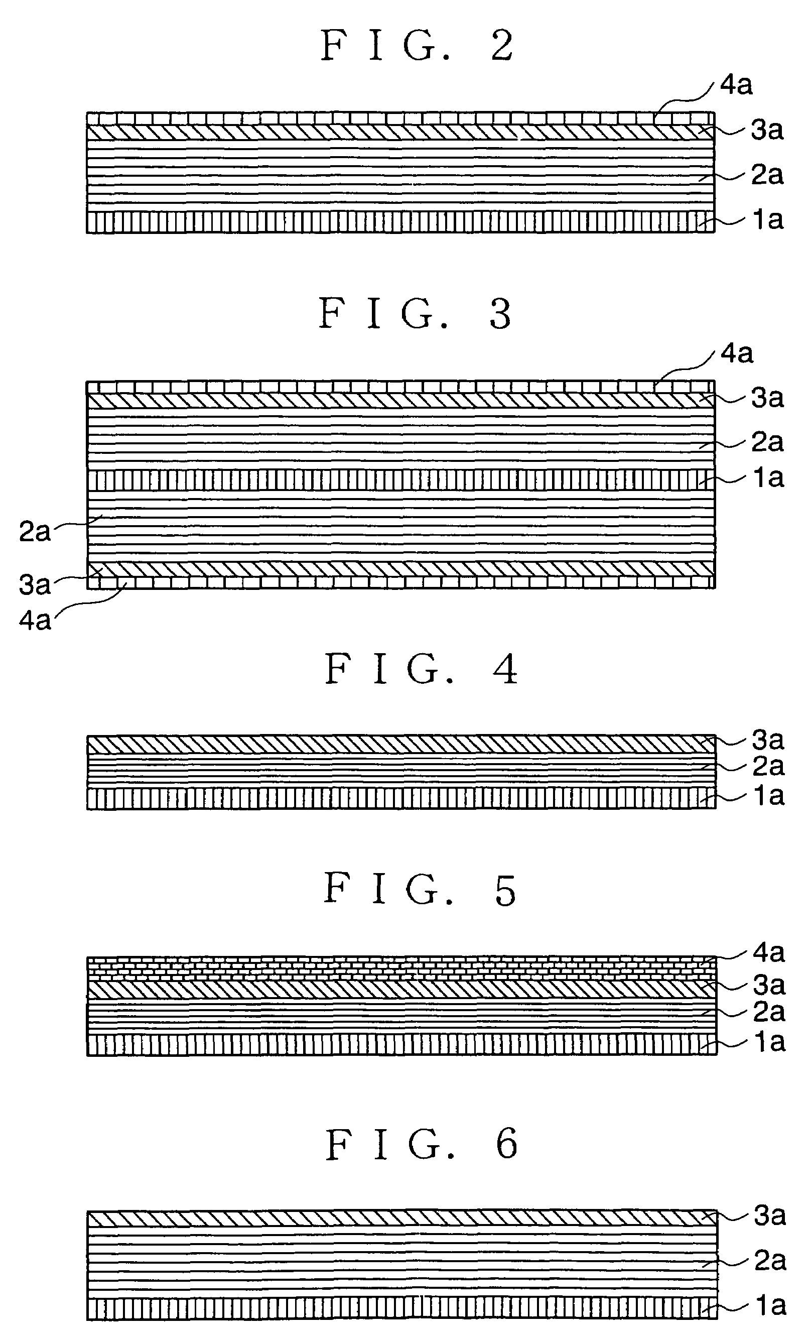
[0109]The anode of the non-aqueous electrolyte secondary battery shown in FIG. 2 was fabricated in accordance with the following procedures. The copper foil having thickness of 10 μm was used as the current collector on which the carbon electrode 2a was deposited. The first anode 2a was prepared by applying, on the current collector 1a, paste obtained by mixing graphite powder with poly-fluorinated vinylidene acting as a bonding agent and dissolved in N-methyl-2-pyrrolidone, and an agent for providing conductivity, followed by drying. After the drying, the first anode 2a was compressed by using a pressing machine. After the second anode 3a made of B2O3...

examples 2 and 3

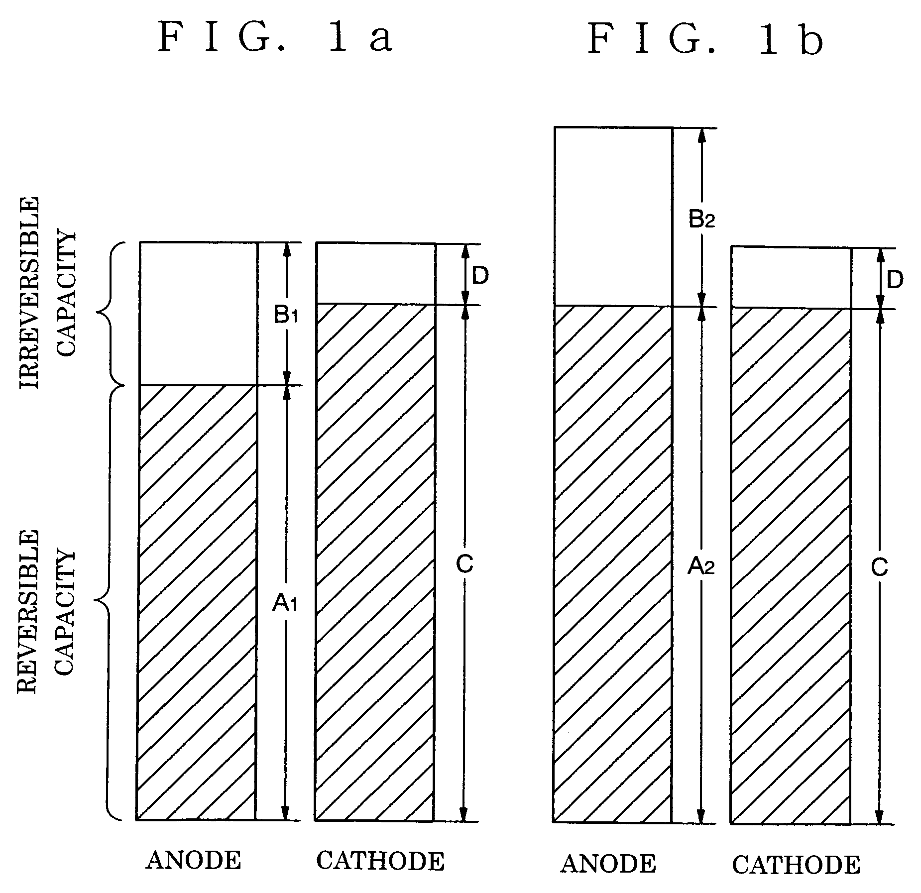
[0124]In these Examples, a copper foil with thickness of 10 μm and hard carbon were used as a current collector 1a and a main components of a first anode layer 2a, respectively. Silicon was used as a second anode layer 3a which was formed by using a CVD method (Example 2) or a sputtering method (Example 3). A third anode layer 4a was made of metal lithium which was formed by using a vacuum-evaporation method. The reversible capacities of the anodes of Examples 2 and 3 were measured by using a coin cell having metal lithium as a counter electrode. A mixed solvent of propylene carbonate (PC) and ethyl methyl carbonate (EMC) dissolving 1 mol / liter of LiPF6 (mixed volume ratio: PC / EMC=40 / 60) was used as electrolyte. Measurement current was 0.1 mA, and a voltage range was 3 to 4.3 V (Li / Li+).

[0125]Non-woven propylene cloth was used as a separator, and a square battery was fabricated by combining the above cathode and anode. The ratios of the reversible capacities of the anodes in the bat...

examples 4 , 5 and 6

EXAMPLES 4, 5 AND 6

[0137]In these Examples, a copper foil having thickness of 10 μm and hard carbon were used as a current collector 1a and the main component of a first anode layer 2a, respectively. As a second anode layer 3a, SiOx (“x” is 0y (“y” is 0x layer and the SnOy layer were formed by using a evaporation method.

[0138]The SiSn layer was formed by using an evaporation method in which Si and Sn were placed in separate crucibles and deposited by using lasers. The ratio between Si and Sn was controlled by measuring the respective amounts of the evaporation with a quartz oscillator.

[0139]Lithium-indium alloy was used as a third anode layer 4a. The amounts of the lithium and the indium in the alloy were 98 weight % and 2 weight %, respectively. The lithium-indium alloy film was formed by using an evaporation method in which the lithium and the indium were placed in separate crucibles and deposited by using lasers. The ratio between the lithium and the indium was controlled by meas...


PUM

PropertyMeasurementUnit
pressureaaaaaaaaaa
distanceaaaaaaaaaa
distanceaaaaaaaaaa

Abstract

An anode for a secondary battery capable of inserting and extracting a lithium ion having a multi-layered structure including a first anode layer containing carbon as a main component; a second anode layer made of a film-like material through which a lithium component passes; and a third anode layer containing lithium and / or a lithium-containing compound as a main component. The battery capacity of the lithium ion battery is substantially increased while the higher charge-discharge efficiency and the stable cycle performance are maintained.

Description

TECHNICAL FIELD[0001]The present invention relates to an anode for a secondary battery, a secondary battery having the anode as its component, and a method for fabricating the anode.BACKGROUND ART[0002]Because of the prevalence of mobile terminals such as a cellular phone and a notebook computer, the role of a secondary battery used for their power sources has been increasing. The secondary battery is required to have the functions such as compactness, lightness, higher capacity and resistance to deterioration after the repetition of charging and discharging.[0003]Metal lithium may be used as the anode of the secondary battery because of its higher energy density and lightness. However, in this case, with the progress of the cycles of the charging and the discharging, needle crystals (dendrite) deposited on the lithium surface during the charging penetrate a separator to cause the internal short-circuit failure, thereby reducing the battery life.[0004]Lithium alloy having a composit...

Claims


Application Information

Patent Timeline
Patent Type & Authority Patents(United States)
IPC IPC(8): H01M4/58B05D5/12C23C14/34H01M4/13H01M4/131H01M4/133H01M4/134H01M4/136H01M4/139H01M4/1391H01M4/1393H01M4/1395H01M4/36H01M4/40H01M4/48H01M10/05H01M10/052
CPCH01M4/134H01M4/36H01M4/366H01M4/583H01M10/0525H01M2004/027Y02E60/122Y02E60/10
Inventor IRIYAMA, JIROYAMAMOTO, HIRONORIMIURA, TAMAKIUTSUGI, KOJISHIRAKATA, MASATOMORI, MITSUHIRO
Owner NEC CORP
Why Eureka
Try Eureka