Magneto-optical recording medium having in-plane magnetizing layer

a magnetic field and recording medium technology, applied in the field of magnetic field recording medium, can solve the problems of high mechanical accuracy, shallow depth of focus, and difficulty in reducing laser wavelength, and achieve excellent jitter properties in reading and high sensitivity to magnetic field

Inactive Publication Date: 2007-04-24
CANON KK
View PDF34 Cites 0 Cited by
  • Summary
  • Abstract
  • Description
  • Claims
  • Application Information

AI Technical Summary

Benefits of technology

[0020]It is an object of the present invention to provide a magneto-optical recording medium suitable for a DWDD readout method, the magneto-optical recording medium having a high sensitivity to a magnetic field and excellent jitter properties in reading out a random signal.

Problems solved by technology

However, it is difficult to decrease the laser wavelength due to heat generation and inefficiency of the light-emitting element.
Moreover, increasing the numerical aperture of the objective lens results in a shallow depth of focus, thus requiring higher mechanical accuracy.
In MSR, however, the signal detection area is small relative to the spot diameter of the readout laser beam, thus causing a significant decrease in the amplitude of the readout signal.
Accordingly, the readout output is generally insufficient.
As a result, it is not possible to accomplish a significantly high recording density relative to the recording density determined by the diffraction limit of the optical system.
However, these magnetic layers are magnetically coupled to each other by an exchange coupling force at temperatures below the Curie temperature of the switching layer; hence, a domain wall cannot move by the domain-wall coercive force of the memory layer, even when the driving force is applied.
A problem with the medium used for the DWDD readout method described above is that decreasing the length of a recorded mark impairs sensitivity to a recording magnetic field.
As a result, the intensities of a demagnetizing field and a stray field also increase, thereby affecting recording.
That is, a variation in the length of a recorded mark caused by the effect of the demagnetizing field and the stray field leads to a pattern-dependent shift of a domain wall, thus impairing the jitter properties in reading a random signal.
In land / groove recording, this problem becomes more serious.
However, when the land / groove recording and narrower track pitch are applied to achieve higher-density recording, the annealing treatment for a guide groove between recording tracks is quite difficult, thus causing problems in reliability.
However, as shown in FIG. 8, in this method disclosed in Japanese Patent Laid-Open No. 9-161321, a film 801 deposited on a groove 802 has a thickness lower than that of a film deposited on a land 803; hence, another problem arises in that the two films deposited on the groove and the land have different properties, especially, in sensitivities to the recording magnetic field.
Consequently, in such a medium for the DWDD readout method, there are conflicting requirements in terms of sensitivity to the recording magnetic field of a minute mark and the jitter properties of a random signal; therefore, it is difficult to balance them.

Method used


Image

  • Magneto-optical recording medium having in-plane magnetizing layer
  • Magneto-optical recording medium having in-plane magnetizing layer
  • Magneto-optical recording medium having in-plane magnetizing layer

Examples


example 1

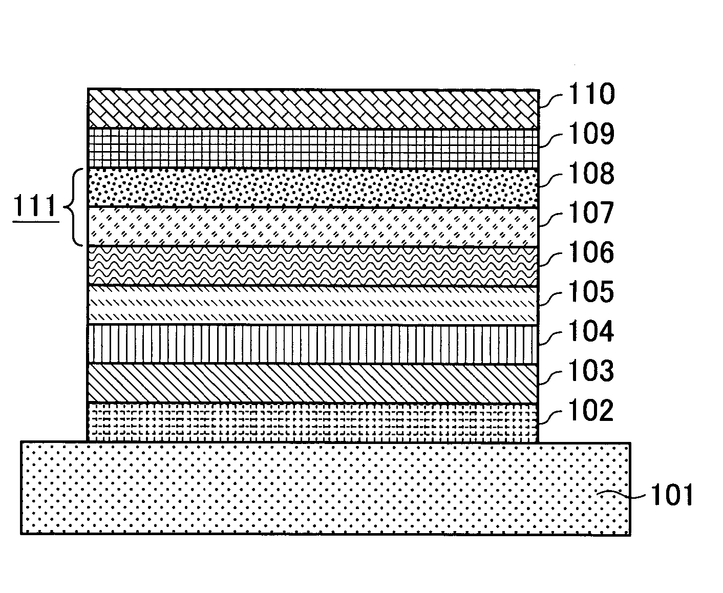
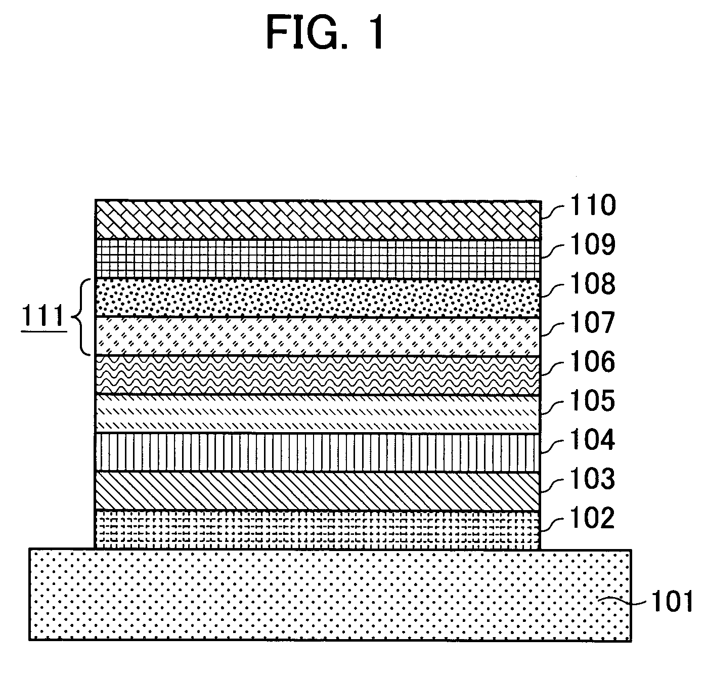
[0043]Targets of B-doped Si, Gd, Tb, Fe, Co, and Cr were mounted in a DC magnetron sputtering apparatus. A land / groove substrate having a track pitch of 0.54 μm and a groove depth of 180 nm was fixed on a substrate holder, and then a chamber was evacuated to a vacuum of 2×10⁻⁵ Pa with a cryopump. Ar gas was introduced into the chamber while the vacuum condition was maintained in the chamber. The targets were sputtered to form layers while the substrate was rotated. A SiN layer was formed by DC reactive sputtering in N2 gas introduced in addition to argon gas.

[0044]That is, Ar gas and N2 gas were introduced into the chamber, and then a desired inner pressure was achieved by adjusting the conductance. A SiN layer having a thickness of 35 nm was formed as the first dielectric layer. The magnetic layers were formed in another chamber because contamination of nitrogen gas causes nitridation of the magnetic layer, which affects the magnetic properties. After the first dielectric layer was...

example 2

[0055]A sample was prepared as in Example 1, but with a change in the Curie temperature of the second auxiliary memory sublayer. As a result, when the Curie temperature of the second auxiliary memory sublayer deviated from the range of 240° C. to a temperature of 40° C. lower than the Curie temperature of the memory layer (in this example, the range 240° C. to 290° C.), the jitter properties and / or sensitivity to a magnetic field deteriorated.

example 3

[0056]A sample was prepared as in Example 1, but with a change in the thickness of the second auxiliary memory sublayer. As a result, when the thickness of the second auxiliary memory sublayer deviated from the range of 5 to 20 nm, the jitter properties and / or sensitivity to a magnetic field deteriorated.


PUM

PropertyMeasurementUnit
temperatureaaaaaaaaaa
thicknessaaaaaaaaaa

Abstract

A high-density magneto-optical recording medium having excellent jitter properties is provided. A pattern-dependent shift of the length of a recorded mark does not occur even when a minute mark has increased sensitivity to a recording magnetic field. A magneto-optical recording medium has at least a displacement layer, a memory layer, and an auxiliary memory layer. A mark with a length up to the diffraction-limit of the optical system is recorded and read out. The magneto-optical recording medium includes an in-plane magnetization-inducing layer principally made of cobalt on the auxiliary memory layer.

Description

BACKGROUND OF THE INVENTION[0001]1. Field of the Invention[0002]The present invention relates to a magneto-optical recording medium having a high areal recording density. In particular, it relates to a magneto-optical recording medium having a high sensitivity to a recording magnetic field.[0003]2. Description of the Related Art[0004]A variety of magnetic recording media have been in practical use as rewritable recording media. In particular, magneto-optical recording media have been deemed promising as mass-storage media capable of high-density recording. There is a known magneto-optical recording medium in which information is recorded by writing magnetic domains in a magnetic thin film by thermal energy of a semiconductor laser and information is read out by the magneto-optical effect. In recent years, along with the trend of digitization of moving images, there have been demands for a larger-capacity recording medium having increased recording density.[0005]Generally, the linear...

Claims


Application Information

Patent Timeline
Patent Type & Authority Patents(United States)
IPC IPC(8): G11B23/03G11B11/00G11B7/24G11B11/105
CPCG11B11/10584G11B11/10591G11B11/10515
Inventor MIYAKOSHI, TOSHIMORI
Owner CANON KK
Why Eureka
Try Eureka