Method and apparatus for multiplexing plural ion beams to a mass spectrometer

a mass spectrometer and multiplexing technology, applied in the field of mass spectrometers, can solve the problems of inefficient use of ions created by direct coupling of continuously operating ion sources to time-of-flight mass spectrometers, uncompromised chemical data, and high overall sample throughput, so as to achieve high throughput and high resolution. , the effect of fast detection

Active Publication Date: 2007-05-15
PERKINELMER HEALTH SCIENCES INC
View PDF11 Cites 45 Cited by
  • Summary
  • Abstract
  • Description
  • Claims
  • Application Information

AI Technical Summary

Benefits of technology

[0044]A further object of the invention is to achieve substantially higher sample throughput on a single mass spectrometer, without mixing the individual analytical samples and without gating various samples in such a way that duty cycle and hence sensitivity might be compromised.
[0047]The timing of multiple analytical samples originating from separate liquid sample streams, ionized by an atmospheric pressure ionization process and delivered into a vacuum system for mass spectrometric analysis may occur in one of three regions. These regions include (a) in the liquid streams themselves, prior to nebulization and ionization, (b) the atmospheric pressure region of an ionization source or (c) in vacuum. For all of these multiplexing strategies one may attain higher throughput than would otherwise be possible using a strictly serial methodology (of one sample introduced to one ion source coupled to one mass spectrometer). However, unlike the other strategies, gating in vacuum affords several features which are analytically useful and unique. The first of these features is the ability to accumulate off-cycle sample (ions) in an ion storage device, thereby preserving the analytical sensitivity of the system for the compound at hand. The second of these features is very short switching time. For circumstances in which one wishes to switch the output of ions from one RF ion guide from “OFF” to “ON” or vice versa, this switch is completed in tens of nanoseconds, a timescale so fast that one may invoke multiple ion guides to switch multiple times every second without significant loss of duty cycle. This second feature is critically important for the invention to service multiple sample streams which may be highly dynamic in nature, such as high speed chromatography exhibiting characteristic peak widths of a second or less in duration. Exacerbating the sampling demand, one may wish to mass spectrometrically analyze several such liquid chromatographs simultaneously, each requiring the acquisition of multiple mass spectra every second. If these chromatographs are all high resolution (i.e. have temporally narrow peaks) and are rapid in nature (multiple peaks occurring in a short period of time) then it is essential that each of these chromatographs be frequently sampled by the mass spectrometer to achieve high chromatographic fidelity, preferably at a rate 5–10 times greater than the typical chromatograph peak width. Unlike other gating strategies shown in Table 1 which must overcome significant time lags while switching between sample streams to accommodate the working fluid (air or liquid solvent), invoking an ion gate in vacuum is essentially instantaneous. This therefore allows one to switch more frequently, which in turn allows one to monitor a larger number of discrete sample streams with adequate fidelity. In contrast, switching between liquid samples using a valve must be done at frequencies of approximately 1 Hz or less in order to avoid excessive carry-over from stream to stream. Also in contrast to the present invention, switching between continuously operating ion sources at atmospheric pressure will require one to several seconds to accomplish, since these partly gaseous, partly liquid sprays needs this time interval to stabilize (i.e. begin to deliver analyte ions to a vacuum orifice) in response to either electrical and / or mechanical shutters.
[0049]In sharp contrast, the present invention may be switched at least as frequently as 1000 Hz, which is suitably fast to detect many dynamic sample streams with adequate chromatographic fidelity. This switching capability makes it ideally suited for a growing number of chromatographic protocols designed for high throughput and high resolution, especially “lab-on-a-chip” based designs.

Problems solved by technology

In this manner, chemical data are uncompromised in terms of cross-stream contamination, while the overall sample throughput is increased substantially.
Given this constraint, the direct coupling of a continuously operating ion source to a time-of-flight mass spectrometer suffers from an inefficient use of the ions created.
While one may apply start pulses to the time-of-flight mass spectrometer at frequencies which match the characteristic time required to re-fill the extraction region from an external supply of ions, duty cycles may still be far from unity under certain conditions.
What has been lacking are the means to accelerate the throughput
However, since all four liquid streams flow continuously, the selection of any one stream necessarily imposes a duty cycle limit dictated by the number of streams sampled.
For those streams which are “off-cycle” (i.e. not sampled) any analytical information contained in the off-cycle portions of those liquid streams is lost and can not be recovered.
Nevertheless, this approach is analytically disadvantageous in circumstances in which sample amounts or concentrations are especially low.
This scarcity of sample will limit the future effectiveness of “lossy multiplexing”, i.e. the use of multiple sample streams multiplexed to a single mass spectrometer with duty cycle limits.
While the chemical specificity of an LC-MS system is greater than using an MS system in the absence of liquid chromatography, there is a time penalty associated with performing an LC separation, reducing the highest achievable sample throughput.
The primary drawback to this approach is the aforementioned uncertainty in ionization efficiency in the presence of possible impurities.
Representative of the current state of the art in high throughput LC-MS, this work clearly shows that radical (order of magnitude or more) improvements in LC-MS throughput, even with specialized chromatographic methods, are not easily obtained when operating in a strictly serial fashion.
However, there are two significant limitations.
In the absence of true sample storage, those LC streams which are not being sent to the mass analyzer at any instant in time are being sent to waste.
Therefore, this time-slicing approach suffers from the fact that by reducing the duty cycle of each effluent stream, the mass analyzer will be rendered blind to peaks which occur off-cycle.
In light of higher speed and higher plate count methods now coming into wider practice, there would be an unreasonably high risk of sending to waste complete peaks which would escape mass spectrometric detection.
There are two limitations in coupling such a system to mass spectrometry in order to achieve higher sample throughput.
One difficulty is the immediate loss in sensitivity due to the duty cycle limit.
Moreover, multiplexing the samples in the liquid phase exacerbates this problem due to the need to introduce inter-sample blanks.
The second difficulty is the inability of the multiplexer to select any given liquid stream at a rate greater than 1 or several Hz.
In instances such as this, mass spectrometric sampling of individual chromatographs at one or several Hz will be inadequate to recreate with any acceptable fidelity the underlying separation.
Because of valve mechanics, this sample selection process is limited in the highest frequency it can operate at while preserving analytically important reproducibility, and moreover creates temporal gaps in the mass chromatograms of the off-cycle streams which may contain analytically important information.

Method used


Image

  • Method and apparatus for multiplexing plural ion beams to a mass spectrometer
  • Method and apparatus for multiplexing plural ion beams to a mass spectrometer
  • Method and apparatus for multiplexing plural ion beams to a mass spectrometer

Examples


Embodiment Construction

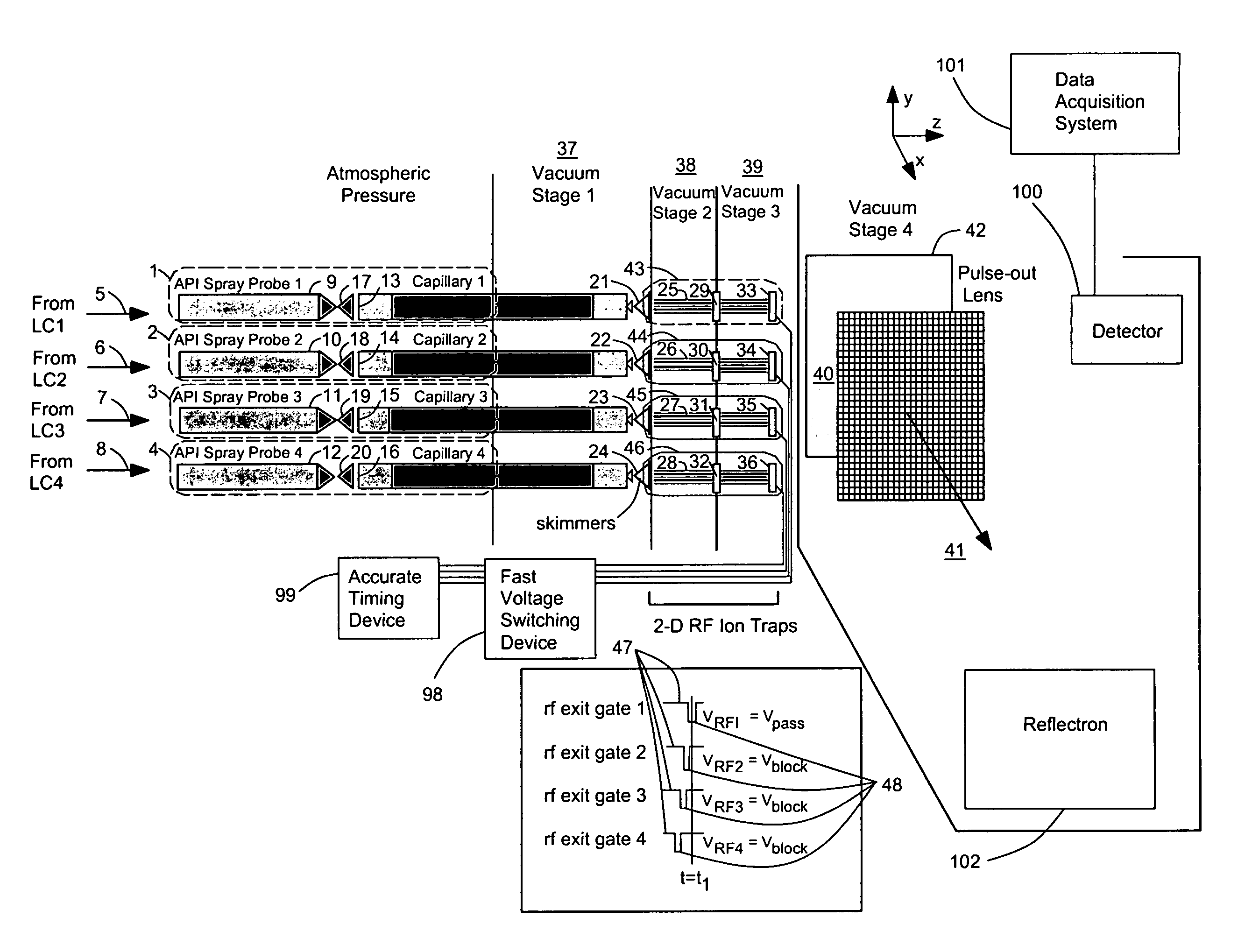
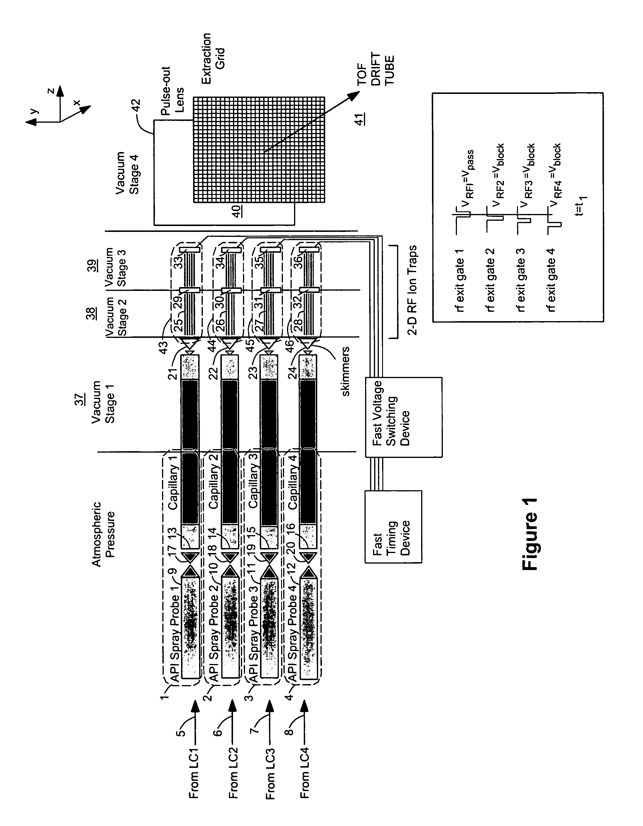
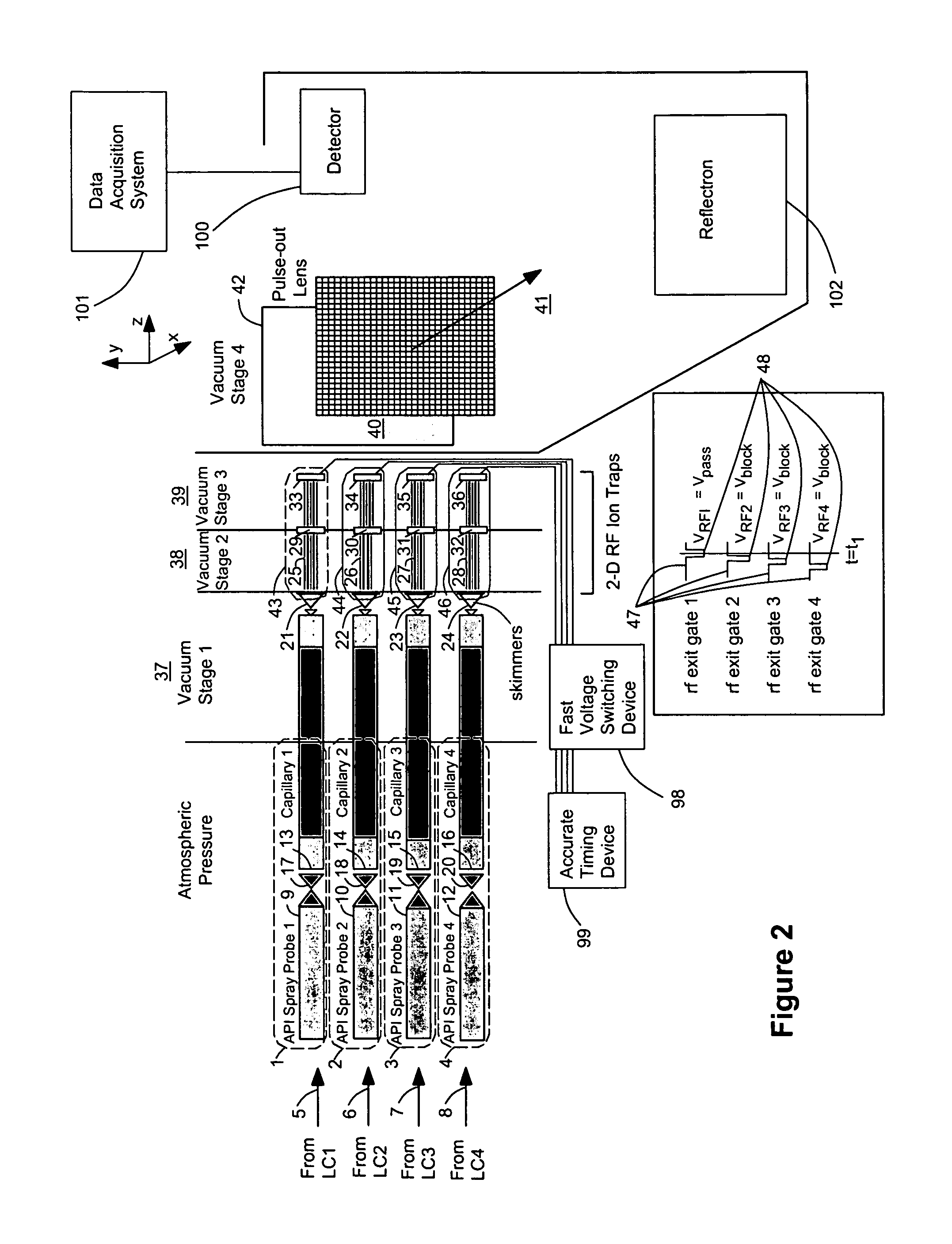
[0058]FIG. 1 shows an arrangement for conducting mass spectrometric analysis on multiple ion sources 1, 2, 3, 4 using a preferred embodiment of the invention. In this case a number of samples are simultaneously injected onto the same number of liquid chromatography columns for separation of their individual constituents. Each of these sample streams 5, 6, 7, 8 elute and are transferred in line to its own atmospheric pressure ionization source 1, 2, 3, 4. These API ion sources 1, 2, 3, 4 are oriented to allow high transfer efficiency of ions between each ionization probe 9, 10, 11, 12 and its respective vacuum orifice 13, 14, 15, 16. Likewise, each of these sprayer-orifice pairs 9&13, 10&14, 11&15, 12&16 is set a suitable distance apart to prevent the migration of ions from, for example, probe A 9, e.g. towards orifice B 14, e.g., which would lead to erroneous mass spectral data in mass spectrum B by falsely indicating the presence of a compound from chromatograph A. Each of the API ...


PUM


Abstract

A method / apparatus for multiplexing plural ion beams to a mass spectrometer. At least two ion sources are provided with means of transporting the ions from the ion sources to separate two-dimensional ion traps. Each ion trap is used for storage and transmission of the ions and operates between the ion sources and the mass analyzer. Each ion trap has a set of equally spaced, parallel multipole rods, as well as entrance and exit sections into which and from which ions enter and exit the trap, respectively. For each ion trap, the entrance section is placed in a region where background gas pressure is at viscous flow. The pressure at the exit section drops to molecular flow pressure regimes without a break in the structure of the ion trap. Each trap alternately stores and transmits ions by way of a fast voltage switch applied to the ion trap exit lens.

Description

[0001]References CitedU.S. Patent Documents3,740,551June 1973Green250 / 41.9 ME3,831,026August 1974Powers250 / 2964,507,555March 1985Chang250 / 2815,179,278January 1993Douglas250 / 2905,331,158July 1994Dowell250 / 2825,420,425May 1995Bier250 / 2925,652,427July 1997Whitehouse et. al.250 / 2885,689,111November 1997Dresch et. al.250 / 2875,763,878June 1998Franzen250 / 2925,811,800September 1998Franzen et. al.250 / 288OTHER PUBLICATIONS[0002]Ooms, B. Temperature Control in High Performance Liquid Chromatography, LC-GC (Asia Pacific), vol. 1, No. 1, p. 27–35 (1998).[0003]Lin H. Y., Voyksner R. D., Analysis of Neuropeptides by Perfusion Liquid Chromatography / Electrospray Ion-trap Mass Spectrometry, Rapid Communications in Mass Spectrometry, vol. 8, p. 333–338 (1994).[0004]Chien, B. M., Michael, S. M., Lubman, D. M., Plasma Source Atmospheric Pressure Ionization Detection of Liquid Injection Using an Ion Trap Storage / Reflectron Time-of-Flight Mass Spectrometer, Analytical Chemistry, vol. 65, p. 1916–1924 (199...

Claims


Application Information

Patent Timeline
Patent Type & Authority Patents(United States)
IPC IPC(8): H01J49/40
CPCH01J49/063H01J49/107
Inventor BOYLE, JAMES G.VALLEY, ROBERT A.
Owner PERKINELMER HEALTH SCIENCES INC
Why Eureka
Try Eureka