
Hypergolic hydrogen generation system for fuel cell power plants

a fuel cell and hydrogen generation technology, applied in electrochemical generators, oxygen/ozone/oxide/hydroxide, chemical production, etc., can solve the problems of reducing the efficiency of the fuel cell power supply, the quantity of carbon monoxide (co) present, and the poisonousness of the pem fuel cell, so as to reduce the formation

Inactive Publication Date: 2008-03-18
CBH2 TECH
View PDF24 Cites 13 Cited by
  • Summary
  • Abstract
  • Description
  • Claims
  • Application Information

AI Technical Summary

Benefits of technology

This approach reduces the overall cost and complexity of the fuel cell system, increases electrical power density, and decreases structural load on the fuel cell stack, while maintaining or exceeding electrical output at lower pressures, thus enhancing efficiency and reducing parasitic loads.

Problems solved by technology

Even when simple hydrocarbons such as methane, methanol, and ethanol are used in hypergolic reactions of hydrogen peroxide and hydrocarbons there may be some quantity of carbon monoxide (CO) present which is poisonous to PEM fuel cells.
Unfortunately, the mechanical devices used to move the air over the cathode represent a parasitic load to the electrical output of fuel cell thereby reducing the efficiency of the fuel cell power supply.

Method used


Image

  • Hypergolic hydrogen generation system for fuel cell power plants
  • Hypergolic hydrogen generation system for fuel cell power plants
  • Hypergolic hydrogen generation system for fuel cell power plants

Examples


Embodiment Construction

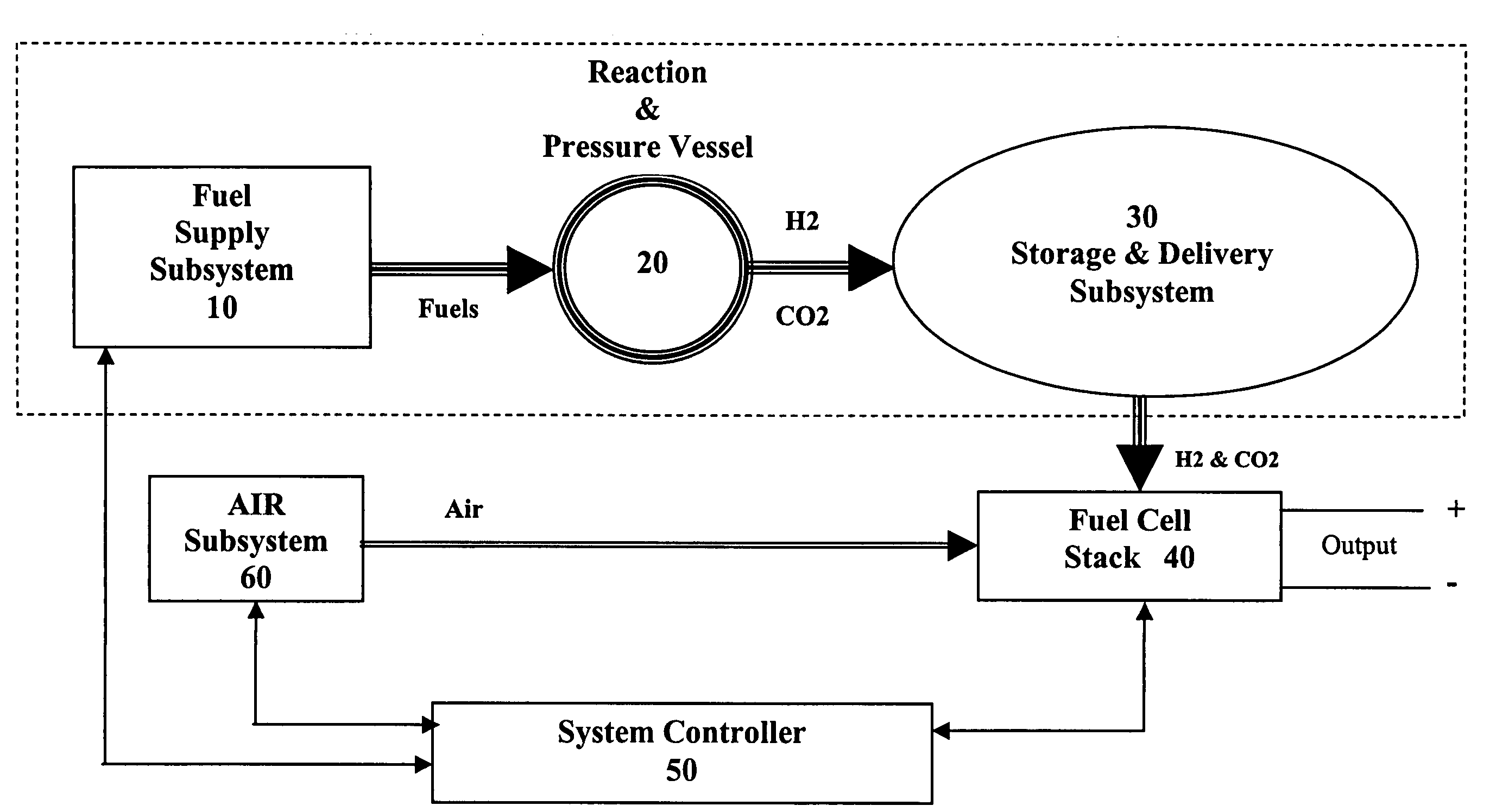
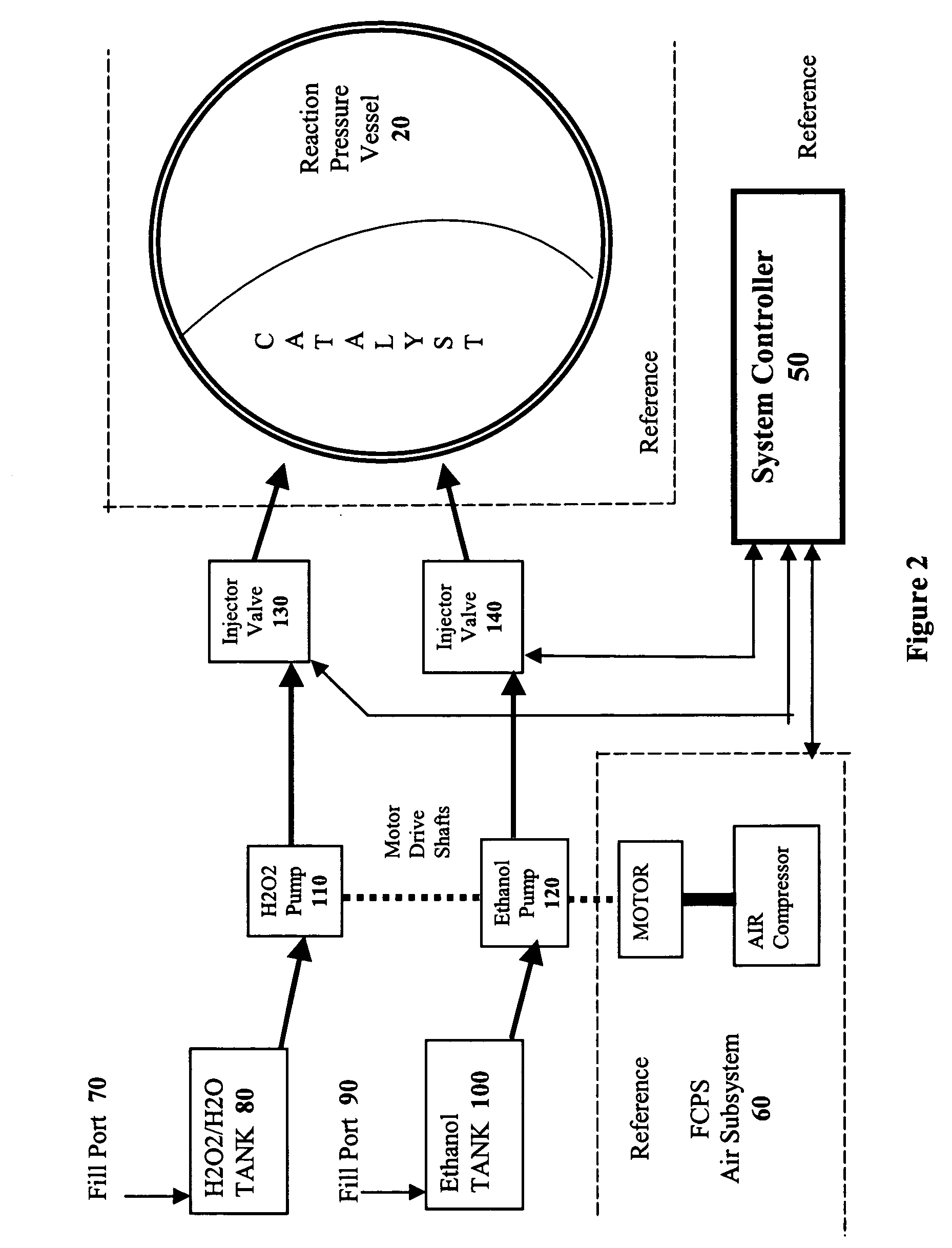
[0022]The present invention takes advantage of the hypergolic reactive nature of concentrated hydrogen peroxide when combined with hydrocarbon fuels in an appropriate stoichiometric ratio to produce carbon dioxide and hydrogen. By combining the fuels in a pressure vessel containing a catalyst that encourages the formation of CO2, hydrogen gas is formed which can then be used to power a fuel cell.

[0023]If simple hydrocarbons such as methane, methanol, or ethanol are combined with H2O2 in the absence of air, the respective chemical reactions are:

H2O2+CH4O→CO2+3H2  (Reaction 1)

H2O2+2CH3OH→2CO2+5H2  (Reaction 2)

H2O2+C2H5OH+H2O→2CO2+5H2  (Reaction 3)

[0024]As shown in Reaction 3, if water is added to the ethanol / H2O2 reaction, the yield is the same as the methanol / H2O2 reaction. Because ethanol is miscible with water, and readily available as a liquid, it is the preferred hydrocarbon source for the methods of the present invention, although one of skill in the art will readily appreciate ...


PUM

PropertyMeasurementUnit
temperatureaaaaaaaaaa
pressureaaaaaaaaaa
pressureaaaaaaaaaa

Abstract

The invention provides a controlled hypergolic approach to using concentrated hydrogen peroxide in combination with certain hydrocarbons such as ethanol, methanol, methane as well as more common fuels such as gasoline, diesel, DME, JP5, JP8 and the like to generate a gas mixture primarily composed of hydrogen and carbon dioxide. Because air is not used as the oxygen source, this novel process does not allow the formation of nitrous oxide (NOx) compounds, thereby avoiding the primary source of nitrogen contamination as well. The process is executed in a constraining system on a micro scale such that the resulting hydrogen supply is self-pressurizing. This enables the incorporation of an “on-demand” hydrogen fuel source for a variable output fuel cell power plant such as those proposed for use in automobiles, marine vessels and stationary power sources. In another embodiment of the present invention hydrogen peroxide is catalytically, or thermally reacted to provide H2O vapor and O2. When this gaseous stream is introduced to the cathode of the fuel cell, the percent concentration of oxygen is increased with no corresponding increase in the parasitic power demand made by an air-moving device. This use of H2O2 as an oxygen source may be continuous, intermittent or limited to specific instances when peak power output demands or high transient loads are placed upon the FCPS.

Description

CROSS REFERENCE TO RELATED APPLICATIONS[0001]This application claims priority to U.S. Provisional Patent Application Nos. 60 / 493,871 and 60 / 503,077 filed Aug. 7, 2003 and Sep. 15, 2003 respectively, which are incorporated herein in their entirety by this reference.FIELD OF THE INVENTION[0002]The invention resides in the field of fuel cell power systems, and specifically methods of generating, storing and metering hydrogen for a fuel cell.BACKGROUND OF THE INVENTION[0003]Fuel cells have the potential to become an economically viable means of converting chemical energy into electrical energy. For example, in a polymer-electrolyte membrane (PEM) fuel cell, also known as a proton exchange membrane fuel cell, hydrogen and oxygen are combined for the production of electrical energy. Air is the customary source of oxygen while the oxidant can be any hydrogen fuel stock including hydrogen, methane, natural gas and ethanol. Other than pure hydrogen, the fuel source may require a local refini...

Claims


Application Information

Patent Timeline
Patent Type & Authority Patents(United States)
IPC IPC(8): C01B3/22C01B3/26H01M8/04C01B3/38C01B3/56C01B13/02H01M8/06H01M8/10
CPCC01B3/38C01B3/56C01B13/0214H01M8/0612H01M8/0662C01B2203/0227C01B2203/042C01B2203/066H01M8/0618H01M2008/1095Y02E60/523Y02E60/50Y02P20/52
Inventor BARBER, JEFFREY L.CRONIN, JEREMIAH J.
Owner CBH2 TECH
Learn More