
Optical sensor with layered plasmon structure for enhanced detection of chemical groups by SERS

a technology of enhanced detection and optical sensors, applied in optical radiation measurement, instruments, spectrometry/spectrophotometry/monochromators, etc., can solve the problems of limiting the sensitivity of such a system, difficult to structurely characterize particles, and inability to reproduce the enhancement degr

Inactive Publication Date: 2008-04-01
POPONIN VLADIMIR
View PDF4 Cites 93 Cited by
  • Summary
  • Abstract
  • Description
  • Claims
  • Application Information

AI Technical Summary

Benefits of technology

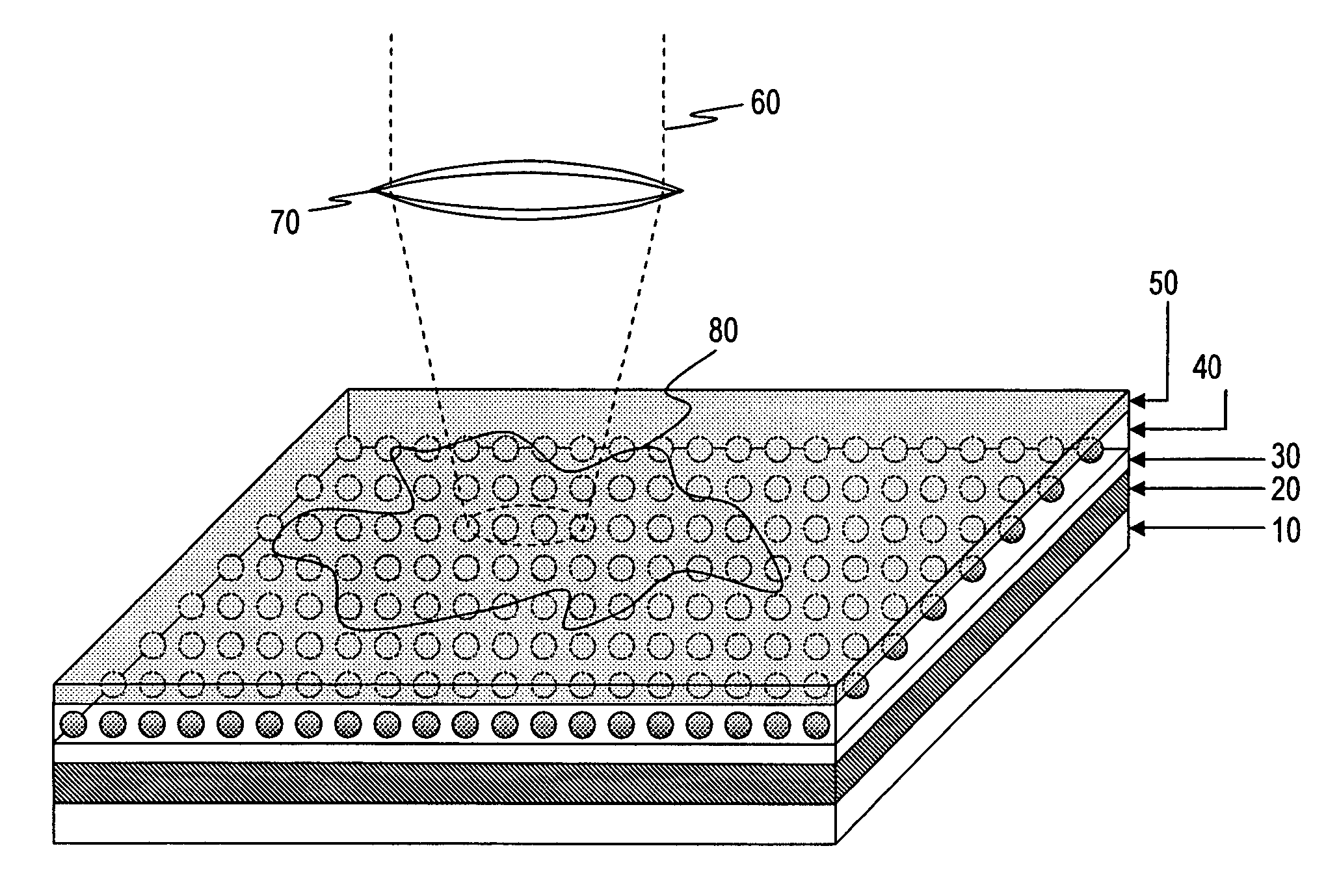
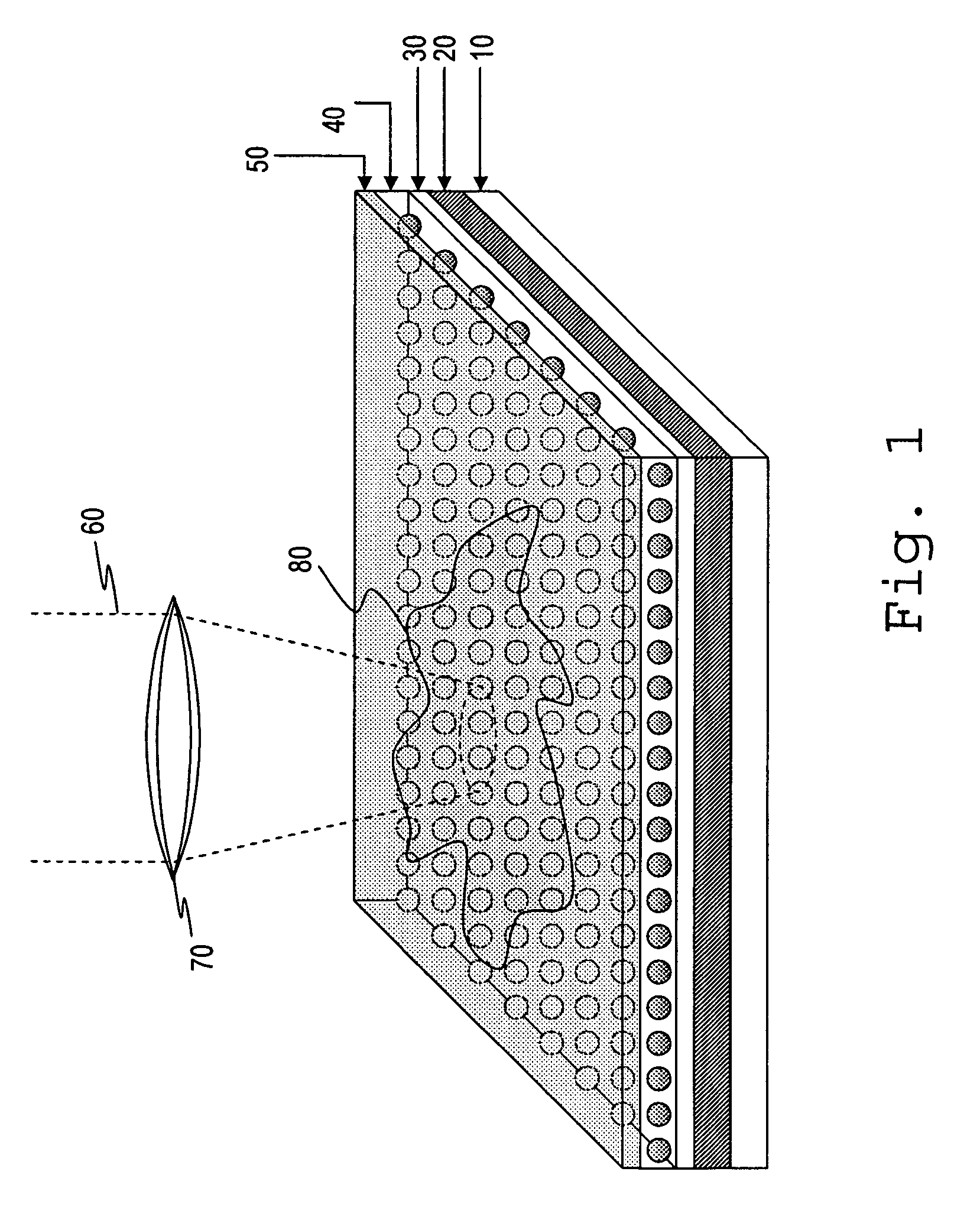
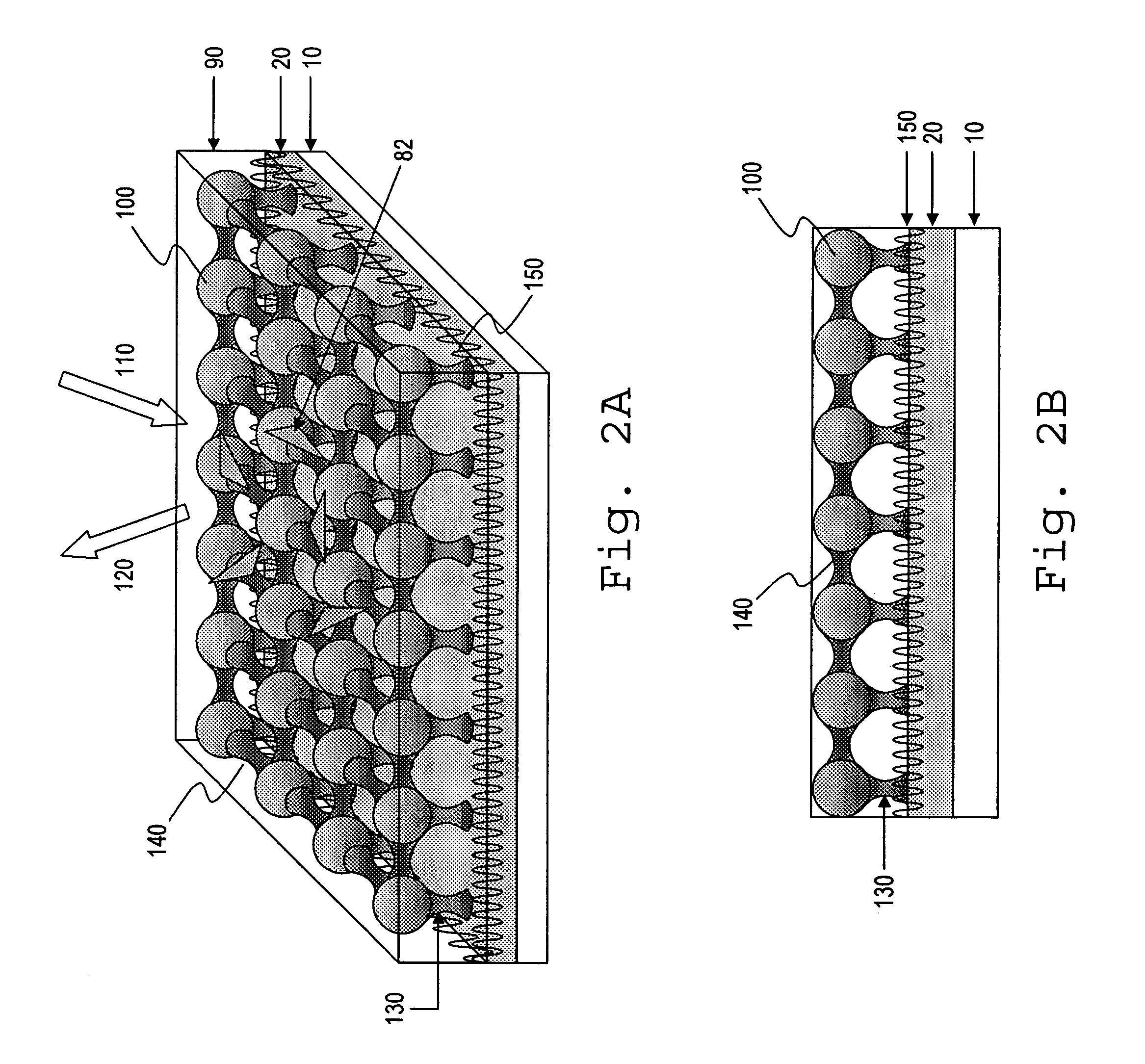
"The present invention provides a plasmon resonance nanostructure that allows for precise control and tunability of its optical response through plasmon resonance effects. This is achieved by using a periodic plasmon layer over a plasmon mirror with an appropriately selected thickness of the dielectric layer. The nanostructure can be used in various applications such as analytical instrumentation and chemical analysis. The plasmon resonance response is controlled by adjusting parameters such as the spacing between layers, the size and shape of the nanoparticles, and the dielectric constant and thickness of the dielectric layer. The nanostructure exhibits high plasmon resonant response and properties of a photonic crystal, resulting in additional effects of focusing and confinement of incident light beam. This allows for a highly reproducible high quality Raman spectra with extremely low excitation power."

Problems solved by technology

The shapes of the metal particles are also variable, so it is difficult to characterization the particles structurally.
In general, the degree of enhancement seen is not uniform across the sensor nor reproducible.
Binger et al., 1995) limits the sensitivity of such a system since MIF-metal substrate structures do not have strong enhancement of Raman signal.

Method used


Image

  • Optical sensor with layered plasmon structure for enhanced detection of chemical groups by SERS
  • Optical sensor with layered plasmon structure for enhanced detection of chemical groups by SERS
  • Optical sensor with layered plasmon structure for enhanced detection of chemical groups by SERS

Examples


example 1

Preparation of a Silver-Silver Particle Nanostructure by Self-Assembly of Ag Nanoparticles

[0117]For each of a number of slides, a silver mirror was deposited on a clean glass microscope slide by thermal evaporation of the silver (99.995%) using vacuum deposition system (E302, Edwards). The slides were immersed in a 1% aqueous polylysine solution for one hour, forming a polylysine dielectric layer over the silver film. Following rinsing in copious amount of water, the slides were exposed overnight to a silver nanoparticle suspension of optical density 5 at extinction maximum of 450 nm. The self-assembly of the silver particles on the surface resulted in the yellow hue (appearance) of the mirrors. The slides were then rinsed with water and exposed to different analytes for various time periods. After the adsorption of analyte molecules slides were interrogated with Raman spectrometer yielding SERS spectra.

[0118]In the second example, silver nanoparticles were adsorbed on the surface o...

example 2

Preparation of Samples with Self Assembled Silver Particle Nanostructure by Microcontact Printing

[0119]In this example, a method of microcontact printing as disclosed for example in reference (H. S. Shin, et. al. “Direct patterning of silver colloids by microcontact printing: possibility as SERS substrate array”, Vibrational Spectroscopy, v. 29, p. 79-82, 2002, H. Fan et al., “Self-Assembly of Ordered, Robust, Three-Dimensional Gold Nanocrystal / Silica Arrays”, Science, 304, 567-571 (2004), was used to form a close-packed array of silver nanoparticles on a silver mirror.

[0120]Silver nanoparticles were prepared by method disclosed in Lee P. C., Meisel, D. J., J. Phys. Chem., 86, p. 3391 (1982), Poly(vinyl pyrrolidone) was used as the capping agent. First, silver nitrate (0.2 g, Aldrich, 99+%) was dissolved into 3 mL ethylene glycohol (Aldrich, 99.8%). 1 g polyvinyl pyrrolidone (Aldrich, MW≅40000) was added into 15 mL ethylene glycohol and the mixture was stirred and heated to 197° C. ...

example 3

Experimental Measurements on the Analyte Rhodamine 6 G (R6G)

[0127]The experimental system set up used in present experiments is shown on

[0128]FIG. 7A-7C. Measurements were carried using Horiba-Jobin Yvon Raman microscope LabRam HR 800.

[0129]Measurement of SERS spectra from liquid samples was carried out using a fluidic cell made from borosilicate glass. A schematic diagram of a fluidic cell is presented on FIG. 7A (top view) and in FIG. 7B (cross sectional view). A glass fluidic cell contains fluidic a channel 84 formed on a glass slide 14 to a depth of about 1.2 to 2.0 mm. The thickness' of the SERS-active structure150 was 0.8 mm. During the experiment, the optimal value of parameters such as depth of fluidic channel was determined, e.g., the best conditions for focusing of the laser light beam through the confocal objective in Raman microscope. Use of the glass cover slip 16 was critical in order to maintain the same thickness of analyte layer during all sets of measurements. As a...


PUM

PropertyMeasurementUnit
sizeaaaaaaaaaa
sizeaaaaaaaaaa
thicknessaaaaaaaaaa

Abstract

An optical sensor and method for use with a visible-light laser excitation beam and a Raman spectroscopy detector, for detecting the presence chemical groups in an analyte applied to the sensor are disclosed. The sensor includes a substrate, a plasmon resonance mirror formed on a sensor surface of the substrate, a plasmon resonance particle layer disposed over the mirror, and an optically transparent dielectric layer about 2-40 nm thick separating the mirror and particle layer. The particle layer is composed of a periodic array of plasmon resonance particles having (i) a coating effective to binding analyte molecules, (ii) substantially uniform particle sizes and shapes in a selected size range between 50-200 nm (ii) a regular periodic particle-to-particle spacing less than the wavelength of the laser excitation beam. The device is capable of detecting analyte with an amplification factor of up to 1012-1014, allowing detection of single analyte molecules.

Description

[0001]This patent application claims priority to U.S. Provisional Patent Application No. 60 / 572,959 filed May 19, 2004, which is incorporated herein in its entirety by reference.[0002]This work was supported in part by U.S. Government Agency and U.S. Department of Defense Air Force Contract No. AFOSR F49620-04-C-0058. The United States Government may have certain rights in this invention.FIELD OF THE INVENTION[0003]The present invention in general relates to a novel optical sensor composed of SERS-active plasmon particles over a plasmon mirror for enhanced localized optical phenomena, and the use of this effect for ultrasensitive chemical and biological sensing with high structural specificity and with high detection sensitivity.REFERENCES[0004]The references below are cited as part of the background of the invention and / or as providing methodologies that may be applied to certain aspects of the present invention. These references are incorporated herein by reference.[0005]G. Bauer ...

Claims


Application Information

Patent Timeline
Patent Type & Authority Patents(United States)
IPC IPC(8): G01N21/65G01J3/44G02B5/20G02B27/10
CPCG01N21/658G02B5/204Y10T436/143333G02B27/10G01N21/65
Inventor POPONIN, VLADIMIR
Owner POPONIN VLADIMIR
Learn More