

Anisotropic conductive connector and wafer inspection device
a technology of anisotropic conductive connectors and inspection apparatuses, which is applied in the direction of connection contact material, semiconductor/solid-state device testing/measurement, instruments, etc., can solve the problems of large size of whole wafer inspection apparatus, high inspection cost, and long time to conduct inspection, so as to achieve stable connection state, good electrical properties, and low contact resistance
- Summary
- Abstract
- Description
- Claims
- Application Information
AI Technical Summary
Benefits of technology
Problems solved by technology
Method used
Image

Examples
production example 1
of Mold
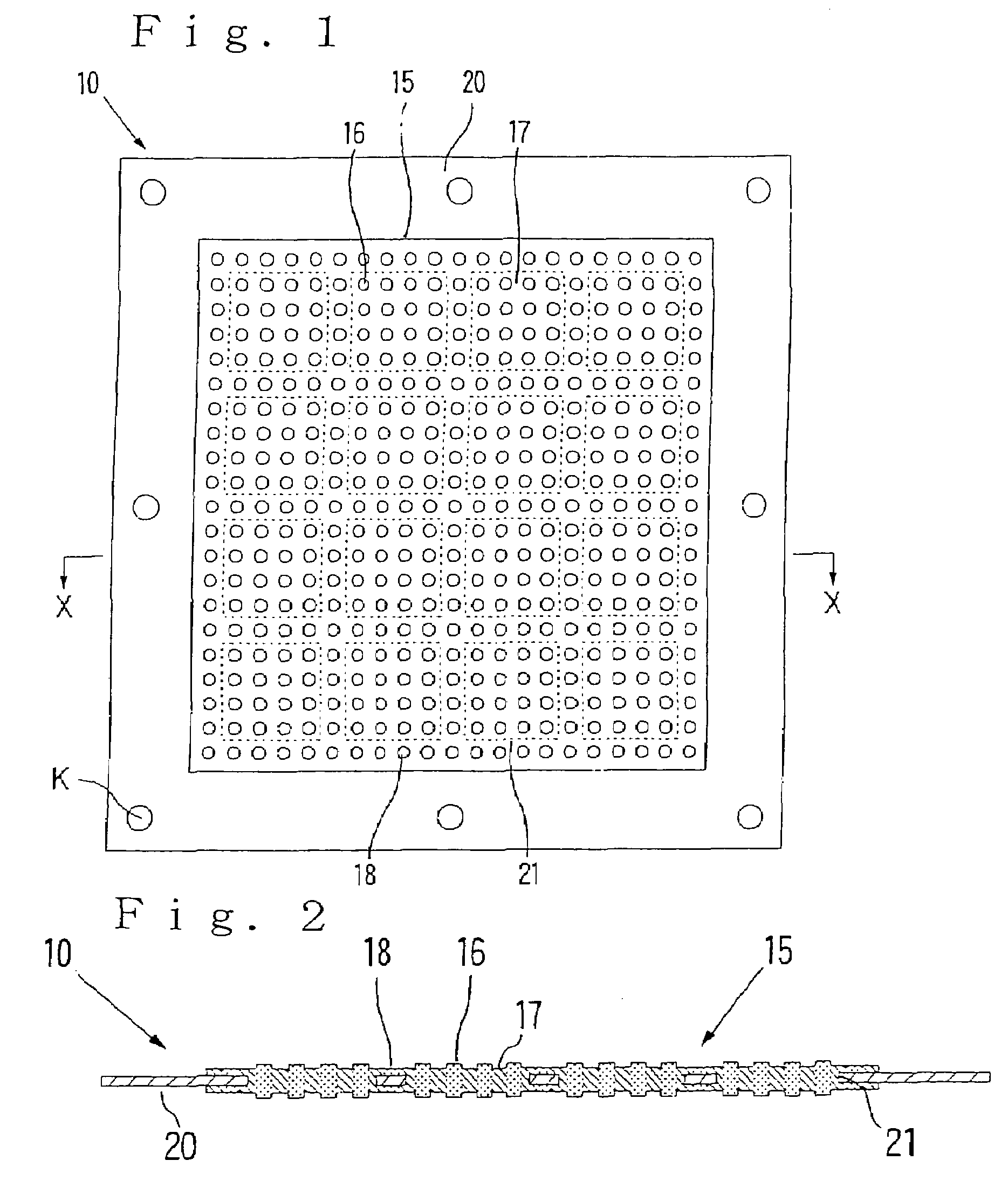
[0267]A brass plate having a thickness of 3.0 mm was provided, a plurality of magnetic member-receiving recesses, which each had a circular section whose diameter was 0.3 mm and whose depth was 2.7 mm, were formed in one surface of such a non-magnetic base plate by a drilling machine at a pitch of 0.8 mm in an X-X direction (the direction means a direction corresponding to the X-X direction in FIG. 1; the same shall apply hereinafter) and a pitch of 0.8 mm in a Y-Y direction (the direction means a direction perpendicular to the X-X direction; the same shall apply hereinafter) and a plurality of projected portion-forming recesses, which each had a circular section whose diameter was 0.3 mm and whose depth was 0.05 mm, were formed in the other surface of the non-magnetic base plate at a pitch of 0.8 mm in the X-X direction and a pitch of 0.8 mm in the Y-Y direction, thereby producing a non-magnetic base plate. A spherical magnetic member made of iron and having a diameter of 0....
production example 2
of Mold
[0269]An iron plate having a thickness of 6 mm was provided, and one surface of this iron plate was subjected to a photo-etching treatment using a dry film resist and ferric chloride, thereby producing an intermediate in which a plurality of disk-like ferromagnetic substance layers each having a thickness of 0.1 mm and a diameter of 0.25 mm had been integrally formed at a pitch of 0.65 mm in the X-X direction and a pitch of 0.65 mm in the Y-Y direction on a ferromagnetic base plate made of iron and having a thickness of 5.9 mm.
[0270]Non-magnetic substance layers each having a thickness of 0.15 mm were formed at other areas than the ferromagnetic substance layers on said one surface of the intermediate by using a resist, thereby making a top force. A bottom force was made in the same manner as in the production of the top force to produce a mold of the construction shown in FIG. 7. This mold is referred to as “Mold b”.
production example 3
of Mold
[0271]An iron plate having a thickness of 6 mm was provided, and one surface of this iron plate was subjected to a photo-etching treatment using a dry film resist and ferric chloride, thereby producing an intermediate in which a plurality of disk-like ferromagnetic substance layers each having a thickness of 0.1 mm and a diameter of 0.40 mm had been integrally formed at a pitch of 1.00 mm in the X-X direction and a pitch of 1.00 mm in the Y-Y direction on a ferromagnetic base plate made of iron and having a thickness of 5.9 mm.
[0272]Non-magnetic substance layers each having a thickness of 0.2 mm were formed at other areas than the ferromagnetic substance layers on said one surface of the intermediate by using a resist, thereby making a top force. A bottom force was made in the same manner as in the production of the top force to produce a mold of the construction shown in FIG. 7. This mold is referred to as “Mold c”.
PUM
 Abstract
Description
Claims
Application Information