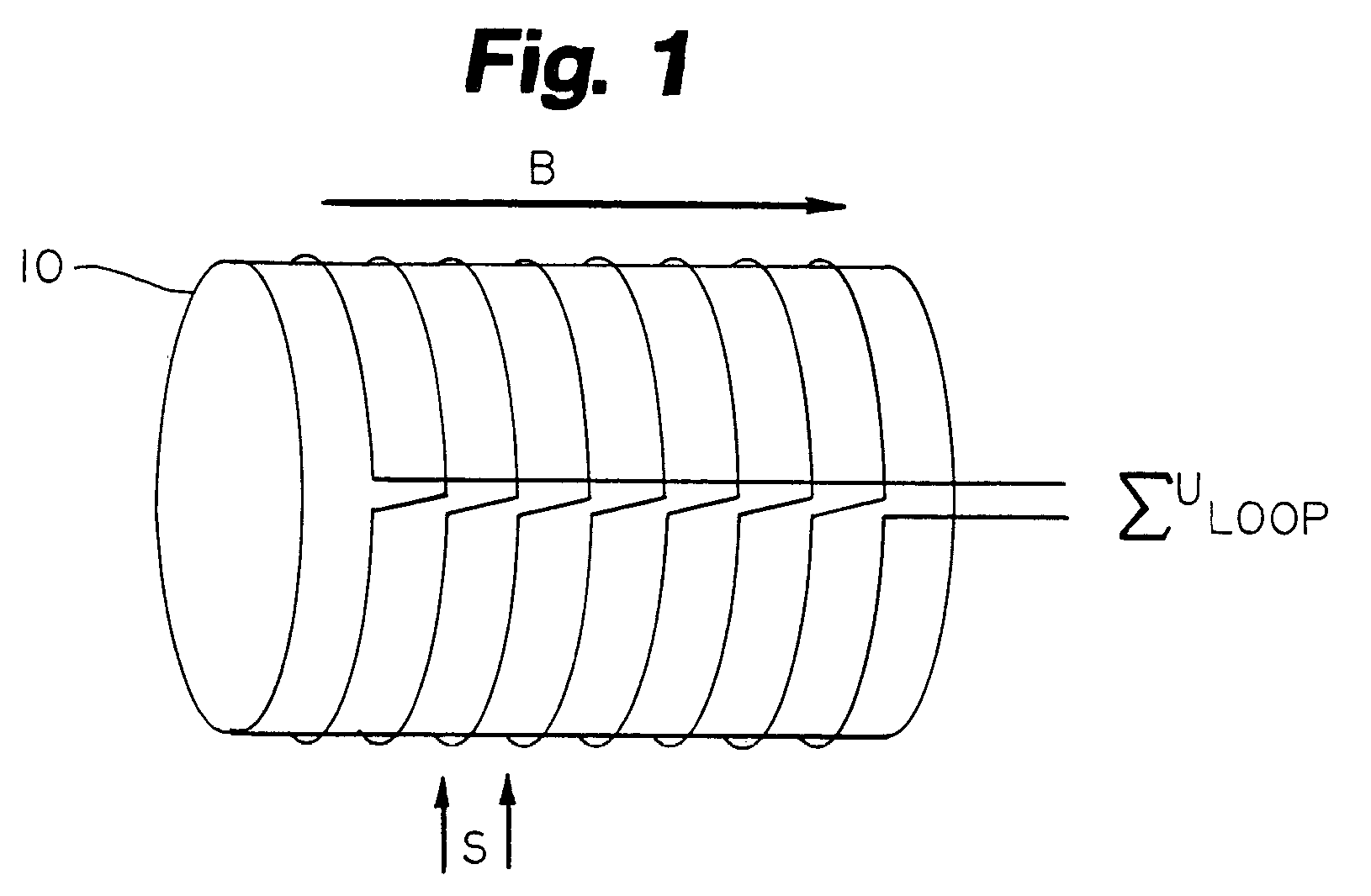
[0030]Summation of the induced voltages is accomplished by electrical serial connection of the loops, effectively reducing the complexity of the
system, since only one
voltage needs to be measured. This is an important
advantage of the invention disclosed herein resulting in reduced system complexity. The choice of the loop spacing s (also referred interchangeably herein as distance d) is a compromise between accuracy and convenience in the design of the volume
transducer. A low value of s means that a higher number of loops will be needed to encompass the measurement region, which typically is from the level of the
axilla and down to the crest of the hips, when measuring a
torso. If the number of loops becomes high, the self-
inductance of the serially connected loops starts to increase dramatically, with implications for the design of the electronic circuits. A preferable embodiment is to use values of s in the range of four to eight cm, which are the smallest values to be used for infants. This typically results in eight (8) to ten (10) loops. Other configurations, however, are possible. The
magnetic field need only be homogeneous within the volume occupied by the relevant parts of the patient's body or other object being measured. Practical experience indicates that a field of sufficient intensity and homogeneity can be generated just by arranging a conductor wire as a vertical rectangular loop, following the floor, walls and ceiling of the room, and feeding an
alternating current through the loop. Preferable values are 10 kHz to 200 kHz with currents below 1 A, although other configurations are possible. For example, more than one
electrical conductor loop may be used.
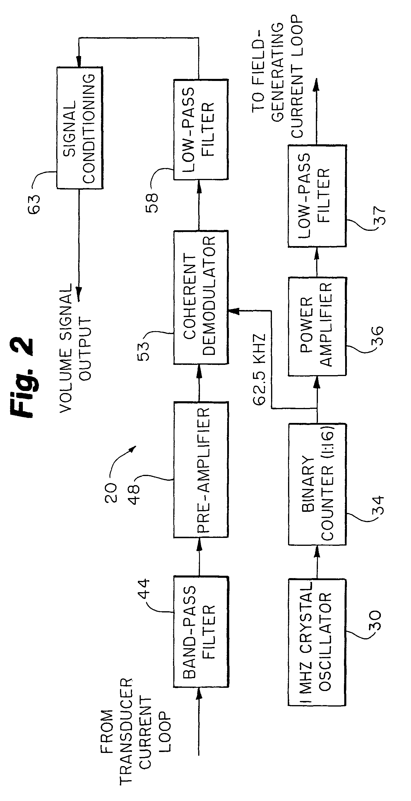
[0031]FIGS. 2-8 relate to a first embodiment of this invention discussed below. This embodiment, shown in
block diagram form in FIG. 2, comprises integrating both the
alternating current source for the
current loop that generates the
magnetic field and the circuits needed to amplify and rectify the returned
signal into a single unit. Stable
crystal oscillator 30 controls system 20, with the output frequency of the oscillator being divided down to the desired value by binary counter 34. The suggested values of 1 MHz and a division of 16 are arbitrary. It is, however, an
advantage that the
signal fed into the power
amplifier 36 is a symmetric
square wave, since this waveform lacks even frequency
harmonics. The removal of unwanted
harmonic frequency components by filter 37 is then easier. Such removal of
harmonics is preferable to avoid
radiation interference with other
electronic equipment. The
amplifier output will eventually be fed into an
inductive load that absorbs almost no energy. By using a (class D) switching
amplifier design, and by proper design of the low-pass filter, the total
power consumption of the amplifier unit can be minimized, reducing the demands for circuit cooling and for power supply capacity. The low-pass filter 37 would likely be a passive one, and would not introduce substantial phase-shifts to the
voltage waveform at the frequency used. The
signal picked up by the serially-connected loops, which in one embodiment are wrapped around a patient as shown and described below in relation to FIG. 6, is first fed into
band pass filter 44. The purpose of this filter is to increase the system
noise immunity. The filter can be designed as a narrow-band resonant
transformer, effectively implementing galvanic separation of the conductive wires close to the patient and the rest of the apparatus.
[0032]Pre-amplifier 48 is useful since the
noise performance of the amplifiers is better than that of demodulator 53. The
gain of the amplifier need not be more than necessary to suppress the
noise of the demodulator, with a typical value of about 20 to 25 dB.
[0033]The coherent demodulator 53 rectifies the alternating voltage signal, and is easily implemented by
CMOS analog switches, such as the CD4016 or CD4066 circuit. Using a coherent demodulator has two advantages. It is very linear over a broad
signal intensity range, and together with low-pass filter 58, a substantial improvement in relation to
noise suppression is achieved. The effective bandwidth of the amplifier chain will be twice the
cut-off frequency of low-pass filter 58, with one example of atypical value of this
cut-off frequency being 5 Hz to 15 Hz, with the highest value suited for infants with a higher natural
respiration rate.
[0034]The signal-conditioning block 63 serves several purposes. It provides amplification of the signal, making it suited for further
processing in a computer-based system. Also, the unit provides some means of coarse adjustment of the amplification, preferably controlled by the analyzing
software. Since the signal at the output of the low-pass filter 58 contains a substantial DC or
constant component (corresponding to the total volume of the body inside the coils), some means of subtracting this component will increase the sensitivity of the system in detecting small volume changes. Such subtraction can be made with an electronic high-pass filter, the
cut-off frequency of which must be substantially below common
respiration frequencies (0.05 Hz or below). In order to shorten the time for the output signal to stabilize at start-up of the system, a means of shortening the
time constant of this filter (by
resistor switching) is desired. In some cases, where slow changes not related to respiration are measured, absolute readouts of volume without any zero subtraction might be desired. Applications of this might be monitoring of
edema development, vascular volume reflexes,
muscle growth or
atrophy, effects of
surgical procedures, etc.
[0035]The electronic circuits described above are easily constructed within less than 50 cm2 of circuit board area, and could be integrated with an A / D converter and interface control circuitry on a plug-in board for an ordinary
personal computer, for example as shown in FIG. 14 below. A complete stand-alone unit could also be made, with the size and complexity being dependent on the amount of signal analysis, presentation capability and storage capacity built into the unit. It should be emphasized that the above illustrative description is for only one embodiment of the invention, with numerous alternate means of practicing the underlying technology also being within the scope of the appended claims. Parts of the function of the suggested
block diagram in FIG. 2 could be implemented using
digital signal processing or other means. At least one alternate construction is to let all
processing of the received signal be digital from and including demodulator 53 with a sampling rate of exactly twice the loop current frequency.


