Photoinitiated grafting of porous polymer monoliths and thermoplastic polymers for microfluidic devices

a technology of thermoplastic polymers and porous polymer monoliths, which is applied in the direction of liquid/fluent solid measurement, peptides, machines/engines, etc., can solve the problems of high cost of multi-step wet fabrication of these microfluidic chips, affecting both the adsorption of other molecules and the reliability of quantitative assays, and persisting problems, so as to prevent significant deterioration in the performance of the device and poor bonding

Inactive Publication Date: 2008-10-07
RGT UNIV OF CALIFORNIA
View PDF18 Cites 46 Cited by
  • Summary
  • Abstract
  • Description
  • Claims
  • Application Information

AI Technical Summary

Benefits of technology

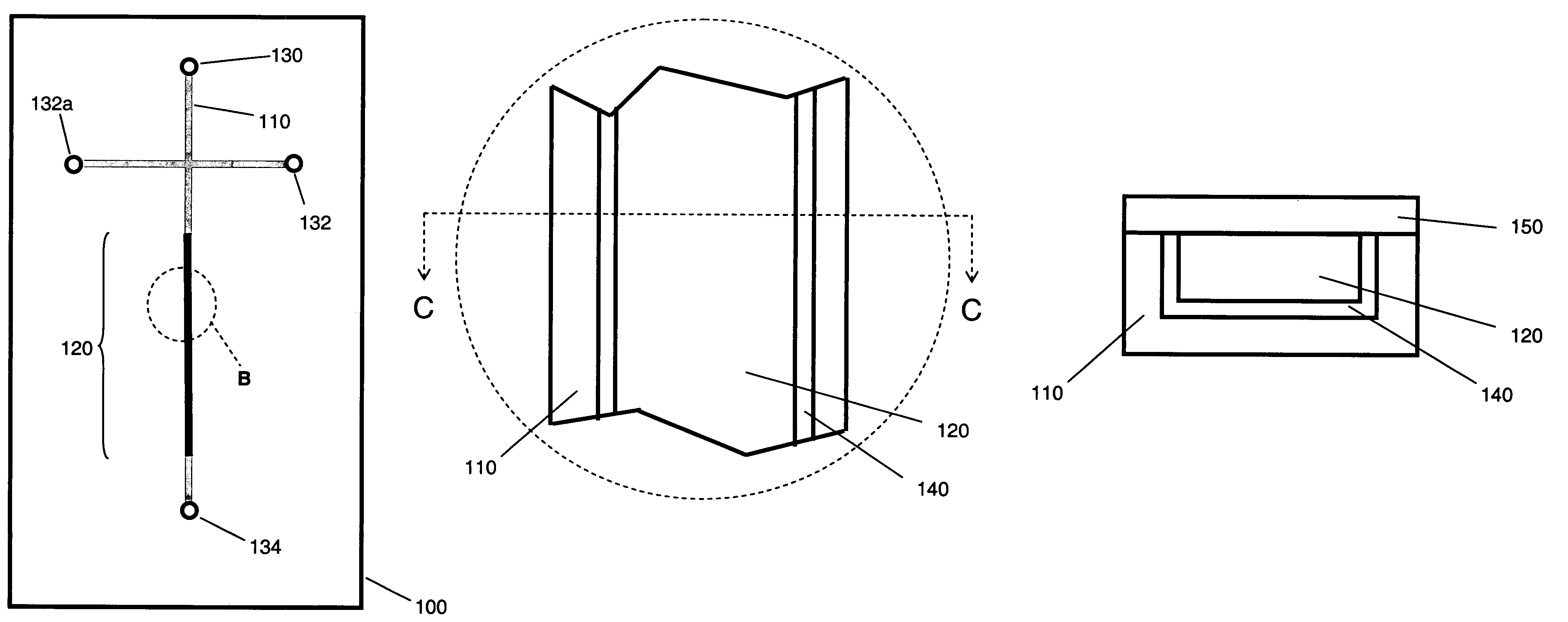
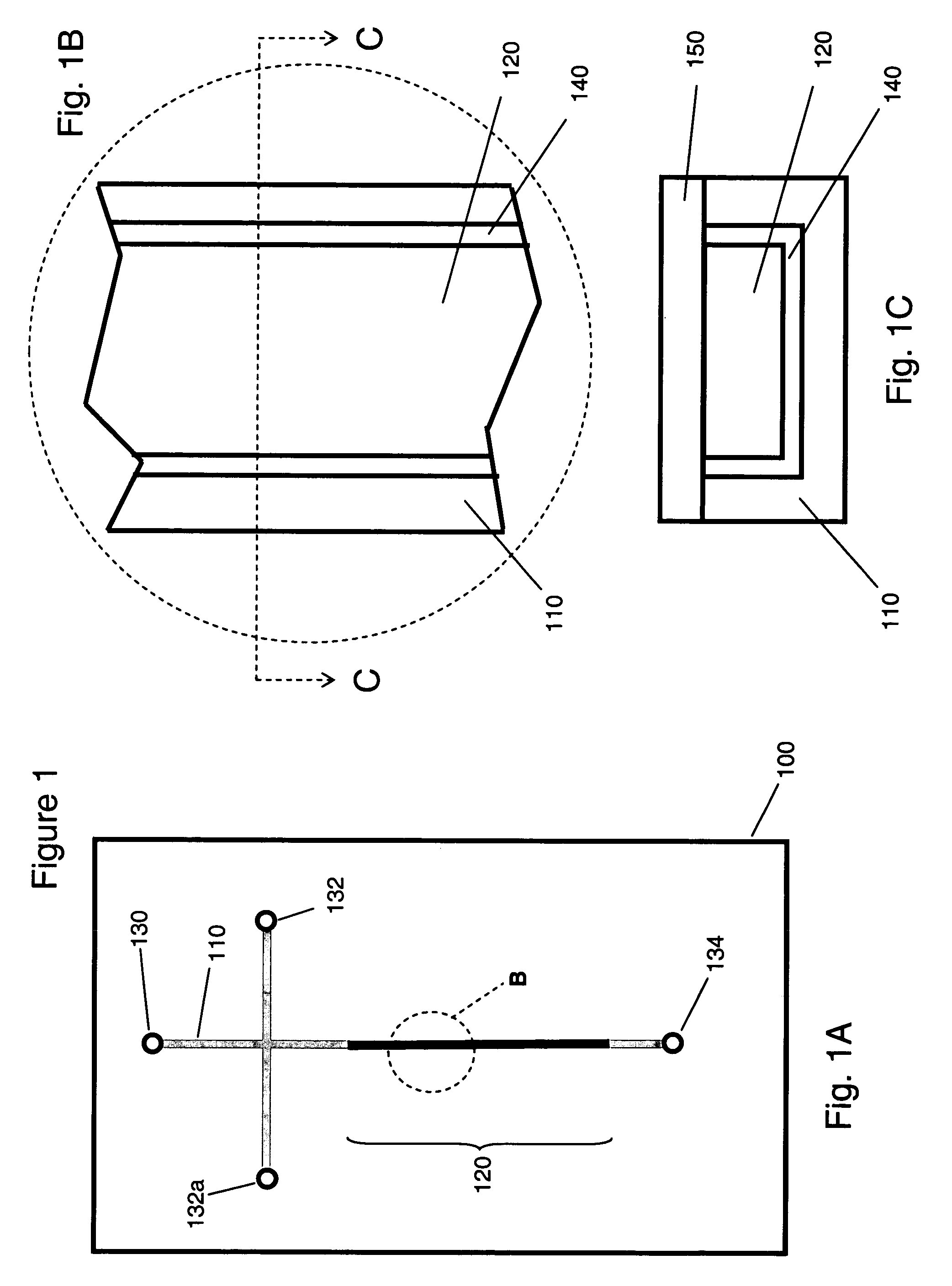
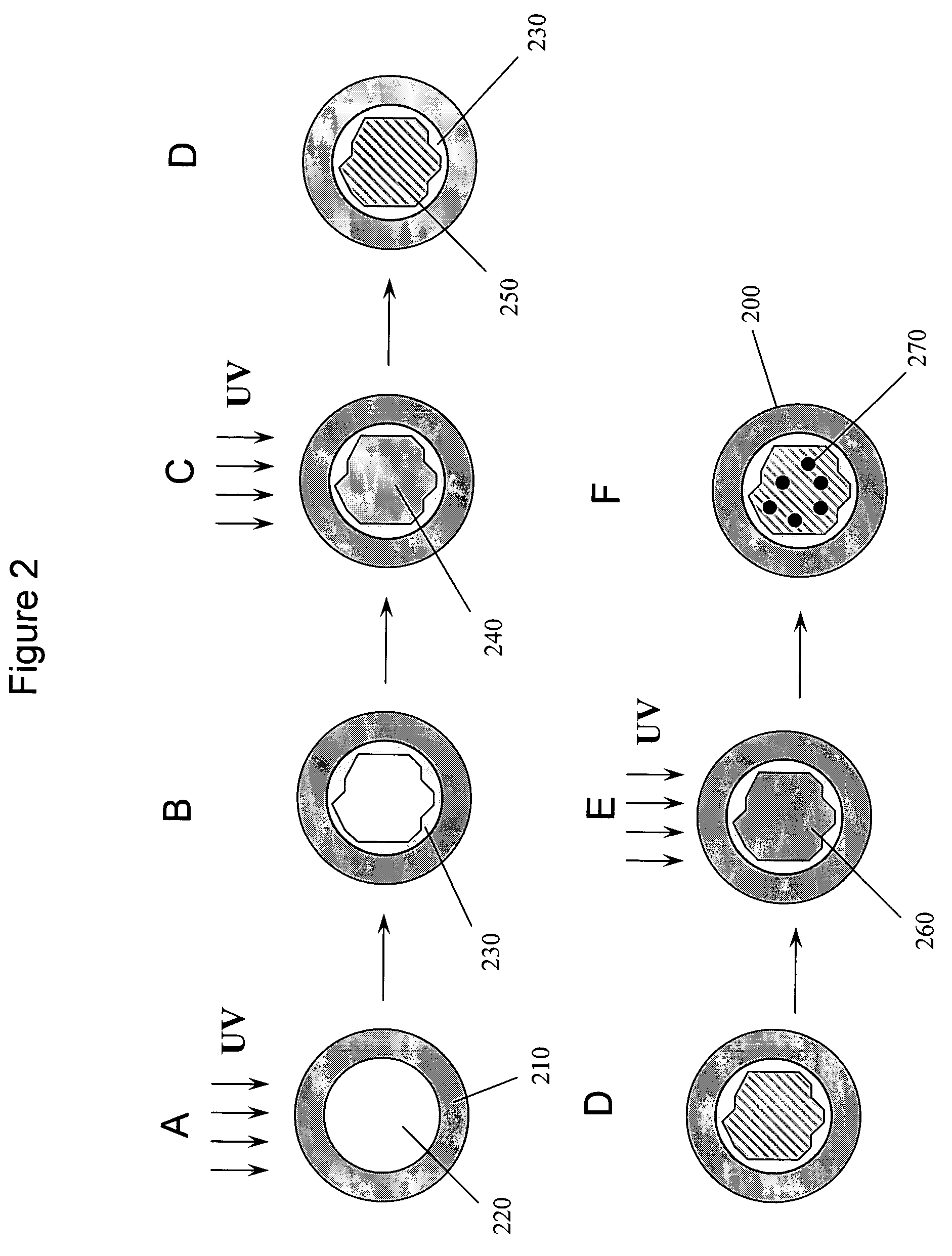
[0015]Modification and surface functionalization of the preferred thermoplastic polymers is accomplished by photoinitated grafting only within a specified space (i.e. a microfluidic channel or a portion thereof), which also permits the layering and patterning of different functionalities on the surface of thermoplastic polymers. This will overcome the poor compatibility of most commercially available thermoplastics and porous monoliths. Poor bonding of the monoliths to surface, e.g. the walls of plastic channels, is prevented, and voids do not develop at the monolith-surface interface thereby preventing significant deterioration in the performance of the devices.

Problems solved by technology

However, the cost of the multistep wet fabrication of these microfluidic chips is high and the use of thermoplastic polymer materials instead of hard inorganics would enable the use of inexpensive ‘dry’ techniques such as injection molding or hot embossing.
In addition, any molecules deposited on the wall of the channel also continuously change the character of the surface further affecting both adsorption of other molecules and the reliability of quantitative assays.
Despite the undeniable success of microfluidic chip technologies in a variety of applications, some problems persist.
This is a serious problem in applications such as chromatographic separations, heterogeneous catalysis, and solid phase extraction that rely on interactions with a solid surface.
However, although photografting has been used for modification of flat two dimensional surfaces, photografting of three dimensional highly crosslinked porous polymer monoliths functionalize or bind them to polymer surfaces has not been demonstrated since these materials were generally assumed to be opaque or diffractive.

Method used


Image

  • Photoinitiated grafting of porous polymer monoliths and thermoplastic polymers for microfluidic devices
  • Photoinitiated grafting of porous polymer monoliths and thermoplastic polymers for microfluidic devices
  • Photoinitiated grafting of porous polymer monoliths and thermoplastic polymers for microfluidic devices

Examples


example1

Screening and Photografting Suitable Thermoplastic Polymer Substrates

[0105]The gray shaded area in FIG. 4 represents the emission spectrum of the UV lamp used and the UV-spectra of polycarbonate (1), poly(methyl methacrylate) (2), polydimethylsiloxane (3), polystyrene (4), cyclic olefin copolymer (5), hydrogenated polystyrene (6), borofloat glass (7) and quartz (8). FIG. 4 shows that quartz (8) is transparent in the entire range, while polycarbonate (1) is completely opaque and therefore not suitable for photografting. The other polymer materials tested all exhibit some transparency within this acceptable range of wavelength between 230-330 nm.

[0106]Among the synthetic polymers, PDMS exhibits the best transparency in the deep UV range. However, its very low Tg makes this material suitable only for limited range of applications such as rapid prototyping. PS-H is also sufficiently transparent and enables acceptable grafting. The UV transparency of COC, a commercially available enginee...

example 2

Monomer Mixtures for Photografting

[0111]The compositions of the acrylamide reaction mixtures used for grafting according to Example 1 are summarized in Table 1. The surfactant PLURONIC F-68 was added to aqueous systems to improve the solubility of benzophenone. All mixtures were deoxygenated by purging with nitrogen for 10 min prior to photografting. Mixtures A, B, C, D, E and F represent different compositions. Mixtures E and F represent the preferred composition of reaction mixture for photografting in the following examples. “BP wt %” indicates the amount of benzophenone used to initiate polymerization.

[0112]

TABLE 1Reaction mixtures used for photograftingReactionAcrylamideBPPluronic F-68mixturewt %wt %wt %SolventAbulk3.00NoneB300.670.67H2OC300.330.33H2OD150.330.33H2OE150.220tBuOH—H2O 3:1F150.220tBuOH

example 3

Photografting Efficiencies and Contact Angles of Acrylamide on Various Substrate

[0113]Photografting of acrylamide on COC using various polymers as filters was performed according to Example 1. Table 2 summarizes the results obtained after 2 min of grafting. Acrylamide was chosen since it contains nitrogen atoms, not present in COC and therefore useful in characterization. In addition, its grafting also changes the polarity of the original hydrophobic surface enabling further measurements for the purpose of characterization.

[0114]

TABLE 2Photografting of acrylamide on COC using various polymers as a filterIrradiation power,mW / cm2a2 min irradiationFilter260 nm310 nmNeffbContact angleQuartz12.512.10.7945Borofloat glass5.89.50.7360PS2.15.60.6261PS-H4.76.80.6755COC7.99.60.7948PDMS6.18.70.7154PMMA0.40.10.3960PC000c   85caTwo probe heads (260 and 310 nm) cover the range between 220 nm and 340 nm shown in FIG. 4.bGrafting efficiency calculated from atomic ratios determined by XPS (N / C found)...


PUM

PropertyMeasurementUnit
wavelength rangeaaaaaaaaaa
thicknessaaaaaaaaaa
wavelength rangeaaaaaaaaaa

Abstract

A microfluidic device preferably made of a thermoplastic polymer that includes a channel or a multiplicity of channels whose surfaces are modified by photografting. The device further includes a porous polymer monolith prepared via UV initiated polymerization within the channel, and functionalization of the pore surface of the monolith using photografting. Processes for making such surface modifications of thermoplastic polymers and porous polymer monoliths are set forth.

Description

CROSS REFERENCE TO RELATED APPLICATIONS[0001]This application claims priority to U.S. Provisional Patent Application No. 60 / 412,419, which was filed on Sep. 20, 2002, which is incorporated by reference in its entirety.STATEMENT OF GOVERNMENT SUPPORT[0002]This work was supported the U.S. Department of Energy under contract No. DE-AC03-76SF00098. The government has certain rights in this invention.BACKGROUND OF THE INVENTION[0003]1. Field of the Invention[0004]This invention relates to microfluidic and fluid handling devices and the modification of pore surface chemistry of porous polymer monoliths and thermoplastic polymers by photoinitiated grafting, surface modification and functionalization.[0005]2. Description of the Related Art[0006]The current rapid development of microfabricated analytical devices is fueled by the need of significant improvements in speed, sample throughput, cost, and handling of analyses. A variety of applications involving, for example, sensors, chemical syn...

Claims


Application Information

Patent Timeline
Patent Type & Authority Patents(United States)
IPC IPC(8): B01L3/02B01L3/00
CPCB01L3/502707B01L2200/12Y10T436/2575B01L2300/0809B01L2300/16B01L2300/069
Inventor FRECHET, JEAN M. J.SVEC, FRANTISEKROHR, THOMAS
Owner RGT UNIV OF CALIFORNIA
Why Eureka
Try Eureka