Solar augmented geothermal energy

a geothermal energy and solar energy technology, applied in the direction of machines/engines, propulsion parts, borehole/well accessories, etc., can solve the problems of solar energy not being able to deliver base load or peak load electrical power, creating steam required for the process, and affecting the efficiency of solar energy production, etc., to achieve the effect of increasing the value of hydrocarbons and their flow rate, and maximizing oil production

Active Publication Date: 2009-01-06
MEKSVANH NINO
View PDF12 Cites 57 Cited by
  • Summary
  • Abstract
  • Description
  • Claims
  • Application Information

AI Technical Summary

Benefits of technology

[0035]The present invention also provides for the in situ fracturing of hydrocarbon molecules to increase the value of those hydrocarbons and their flow rates.
[0038]An additional aspect of the present invention is to provide a method of producing, for long periods of time, a reliable water source for large regions in the United States and abroad.

Problems solved by technology

One difficulty associated with reliance on solar energy is the variability associated with this type of energy production.
For this reason, solar energy cannot be relied upon to deliver base load or peak load electrical power.
One problem associated with steam flooding is the creation of the steam required for the process.
As would be appreciated by those skilled in the art, the cost of steam generation is quite high.
Since steam generation is very cost intensive, requiring significant amounts of natural gas or liquid hydrocarbon combustion to generate the steam, steam flooding of large pro-ration fields (i.e., greater than 20 acres per well) has not been relied upon widely.
Simply, the heat lost to the reservoir strata and resultant ineffective thermal drive has been prohibitive to the application of steam flooding under these circumstances.
However, as noted above, the cost associated with long term steam flooding does not support the use of this method for application to large pro-ration unit fields.
A significant problem with the use of waste water is that waste water is considered an environmental hazard.
Moreover, spills of brine waste water require remediation.
As would be appreciated by those skilled in the art, geothermal production of electricity has been limited to igneous terrains.
Permeability of the igneous terrains and a lack of water resources have presented significant obstacles to this type of energy production.
Insufficient permeability has proved a particular difficulty in hot dry rock technology where rock with a low thermal conductivity immediately adjacent to induced fracture surfaces is rapidly depleted of its thermal charge.
Heat budget management has also proven a problem in geothermal projects.
The capacity to extract heat from a geothermal source often exceeds the natural heat flow within the rocks, resulting in decreased plant efficiency and extinction of associated hydrothermal phenomenon, such as geysers and hot springs.
Even though the hot pressurized geothermal fluid is relatively benign from a chemical perspective, flashing geothermal fluid into steam at the surface can result in a release to the environment of small amounts of environmentally undesirable dissolved materials such as hydrogen sulfide, boron, arsenic, selenium, mercury, lead, and other trace elements and compounds, which are common to and occur naturally in the igneous or metamorphic host rock.
Equally significant, quantities of silica, chlorides, and carbonates are also typically dissolved in the aqueous geothermal fluid, potentially causing corrosion and undesirable deposits (i.e., scale) on turbine blades and other metallic surfaces in power plants and in heat exchangers.
As the critical point for water is reached and then surpassed, the enhanced dissolution of silica, followed by retrograde precipitation below 374° C. and 22 MPa, presents a substantial obstacle to operating an igneous geothermal reservoir at higher than the critical temperature.
The silica dissolution and re-precipitation problem occurs as the critical temperature for water is passed.
Although drilling systems are capable of reaching rock temperatures in excess of 400° C., concerns about enhanced geothermal interactions arise in water based igneous geothermal energy systems at these temperatures.
In summary, the prior art associated with the production of electricity from solar energy, geothermal energy, and hydrocarbon combustion present specific problems that are, as yet, unaddressed.

Method used


Image

  • Solar augmented geothermal energy
  • Solar augmented geothermal energy
  • Solar augmented geothermal energy

Examples


example 1

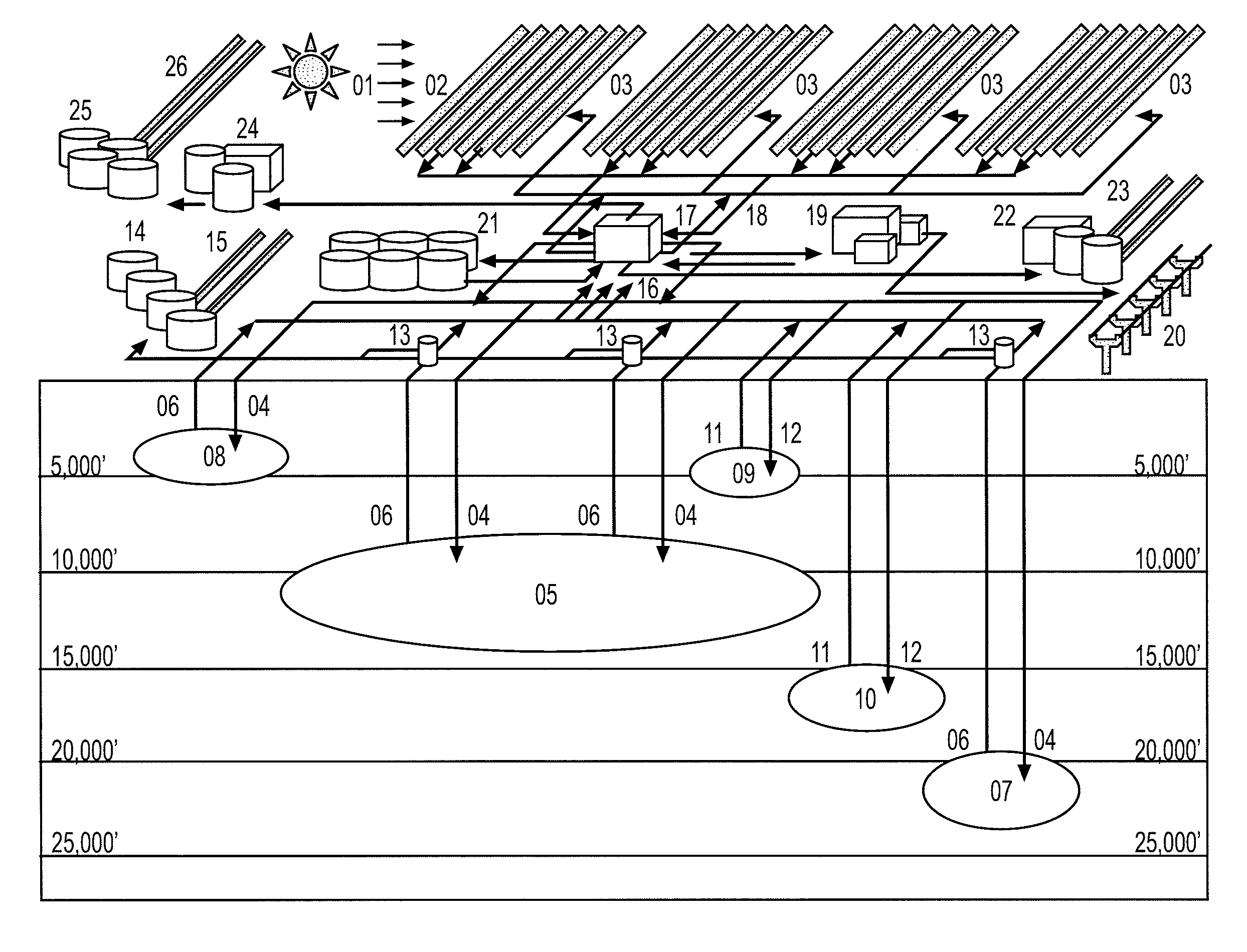
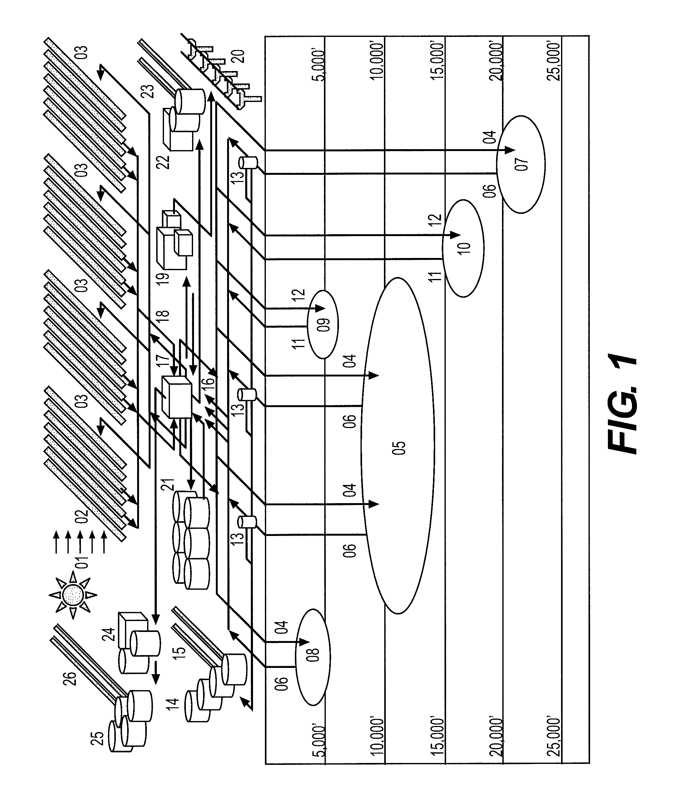
[0131]In a constructive reduction to practice using data from an analogous solar energy production system, the present invention utilizes subsurface storage of solar energy in porous and permeable strata. The present invention utilizes established permeability and porosity in existing and depleted oil and gas fields, along with their hydrocarbon trapping geometries and in place well bores.

[0132]In the hydrocarbon reservoir strata of the Permian Basin of West Texas, permeability ranges from 2 to over 600 millidarcies. Average porosity ranges from 5 to 21%. Water saturations, which is an indication of available oil field brines, range from 25 to 61%. It should be noted that many of the hydrocarbon reservoirs of the Permian Basin are water driven with flank wells being plugged (or capped, i.e., taken out of production) when the water fraction in the effluent from the wells exceed 95%. Many dry holes have been plugged after 100% water effluent was obtained from these permeable and porou...

example ii

[0138]In a constructive reduction to practice, the present invention is applied to a depleted gas field for immediate development of electrical power, water distillation, and / or other traditional geothermal energy uses.

[0139]On a project by project basis, individual wells may be selected for injection, extraction, or abandonment (plugging of wells deemed unfit for conversion, in order to maintain reservoir pressure and flow integrity). Those wells deemed unfit for conversion may be plugged at lower depths and converted to brine source wells from brine bearing strata well above the targeted thermal reservoir 5.

[0140]The system is then charged with oil field disposal brines and / or natural subsurface brines produced from zones above and / or below the reservoir 5. It should be noted here that many deep depleted gas fields in the United States already have a significant geothermal reserve, bottom hold temperatures often exceeding 150° C. This will assist the efficiency of the present inve...

example iii

[0142]The present invention can be applied to non-producing regions or structural traps which have proven non-productive. These projects will carry a risk associated with limited data and the costs of drilling wells specifically for injection and extraction, rather than converting existing wells. These sites provide the advantage of having the potential to employ the teachings of the present invention, including both establishment of drilling pattern and borehole design tailored to synthetic geothermal injection and extraction.

[0143]It should be noted here that drilling of wells in sedimentary basins is significantly less costly, by a factor of 4, than the drilling of comparable depth wells in a traditional igneous or metamorphic geothermal terrain.

[0144]It is anticipated that initial implementation of the present invention will be undertaken utilizing existing oil and gas fields, depleting or depleted. That development will establish the economic parameters necessary to commerciall...


PUM


Abstract

An apparatus and a method is disclosed for storage of solar energy in a subsurface geologic reservoir. The method includes transferring concentrated solar thermal energy to a fluid, thereby generating a supercritical fluid. The supercritical fluid is then injected into the subsurface geologic reservoir through at least one injection well. The subsurface geologic reservoir may be a highly permeable and porous sedimentary strata, a depleted hydrocarbon field, a depleting hydrocarbon field, a depleted oil field, a depleting oil field, a depleted gas field, or a depleting gas field. Once charged with the supercritical fluid, the subsurface geologic formation forms a synthetic geothermal reservoir.

Description

CROSS-REFERENCE TO RELATED APPLICATIONS[0001]This Non-Provisional U.S. Patent Application relies for priority on U.S. Provisional Patent Application Ser. No. 60 / 607,970, which was filed on Sep. 8, 2004, the contents of which are incorporated herein by reference in its entirety.BACKGROUND OF THE INVENTION[0002]1. Field of the Invention[0003]The present invention relates to a method and apparatus for storage of solar energy within an artificial or synthetic geothermal environment. The present invention also relates to the creation and utilization of thermal reservoirs for the synthetic geothermal storage of solar energy, to secondary and tertiary oil recovery, and to the use of those thermal reservoirs for water distillation and continual, or sustained, energy production.[0004]2. Description of the Related Art[0005]Various methods of the production of energy from solar energy are known. In connection with the production of energy from the sun, methods have been developed to concentrat...

Claims


Application Information

Patent Timeline
Patent Type & Authority Patents(United States)
IPC IPC(8): F03G7/00B60K16/00
CPCE21B41/0057E21B43/24F24J2/07F24J3/085F28D20/0052Y02E10/14Y02E10/41Y02E60/142Y02E70/30F24S20/20F24T10/20Y02E10/10Y02E10/40Y02E60/14
Inventor MEKSVANH, SOVANIWHELAN, RONALD P.SWIFT, DOUGLAS B.
Owner MEKSVANH NINO
Why Eureka
Try Eureka