
Emissive species for clinical imaging

a technology of emissive species and clinical imaging, applied in the field of emissive species for clinical imaging, can solve the problems of limiting the use of emissive species in long-term imaging of live cells, difficult long-term monitoring, toxic, etc., and achieves the effects of reducing intermolecular - interactions, high fluorescent intensity, and relaxing constraints on nanoparticle fabrication

Inactive Publication Date: 2009-04-21
FLIR DETECTION
View PDF4 Cites 38 Cited by
  • Summary
  • Abstract
  • Description
  • Claims
  • Application Information

AI Technical Summary

Benefits of technology

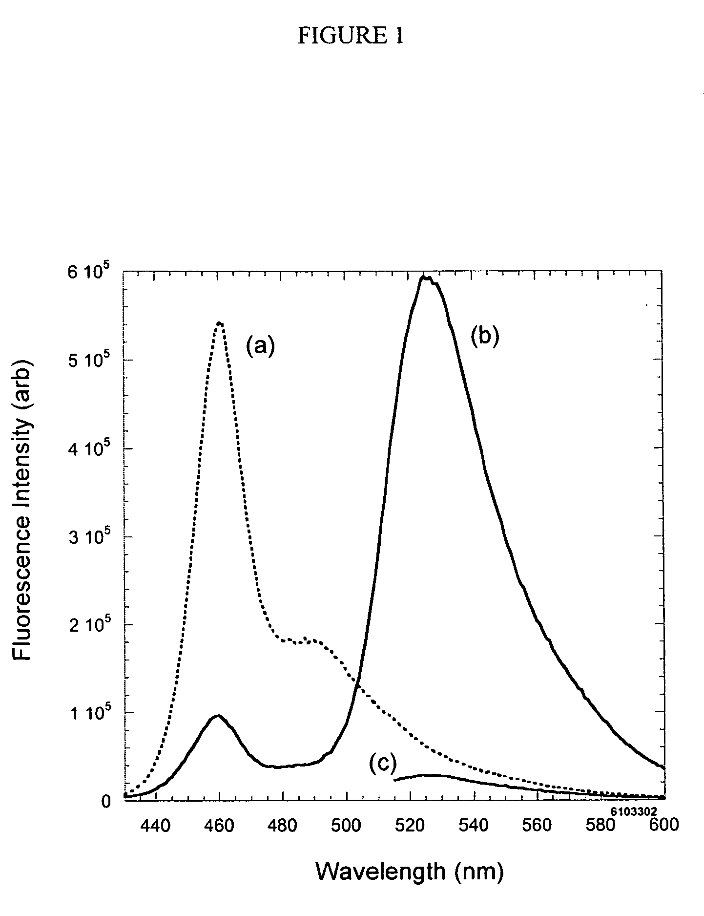
[0068]One advantage of the present invention may be that, in some embodiments, the emission of the conjugated polymer or oligomer is not dependent on the size of the nanoparticle. Quantum confinement of excitons within the inorganic nanoparticle provides precise control over the energy of the particle emission. This constrains nanoparticle manufacture as one must carefully control the size and, more importantly, the size distribution of particles in order to produce particles with a reproducible, narrow emission. In contrast, some embodiments of the invention employ materials designed to minimize intermolecular π-π interactions. Thus, as a solvated polymer chain may be condensed to a solid, the shape of their fluorescence emission may change little and, although some attenuation may be seen in quantum efficiency, the materials may remain highly fluorescent. This feature may be advantageous since the emission of the material may not be dependent on nanoparticle size. This significantly relaxes constraints on nanoparticle fabrication and processing as polydispersity in nanoparticle size will have little effect on the polymer emission. In some embodiment, only 7-10 monomeric units may be needed to preserve minimum photophysical properties.
[0069]The conjugated polymers and oligomers of the present invention may further comprise a biological recognition entity. As used herein, a “biological recognition entity” may be any biomolecule capable of having a recognizing interaction with a cell, cell membrane, or species associated with a cell. A “recognizing interaction” typically will involve biological specific or non-specific binding such that the recognition entity will recognize and interact with a cell, cell membrane, or species associated with a cell uniquely, that is, reacting with that cell or species preferentially rather than with other similar cells or species. Those of ordinary skill in the art understand this terminology and how to select recognition entities suitable for use in the context of the present invention.
[0070]In one embodiment, the biological recognition entity is a peptide (e.g., a cell-penetrating peptide). Examples of suitable peptides include PPKKKRKVPPKKKRKV from SV40 large T antigen protein, an oligomeric peptide sequence YGRKKRRQRRR, protein transduction domain (PTD) from the human immunodeficiency virus TAT protein, and random peptide sequences of EPPLSQEAFADLLKKK, other synthetic peptides, natural peptides, cationic peptides, and peptides derived from viral, inset, or mammalian proteins endowed with membrane translocation properties. Short peptides derived from protein-transduction domains are known to achieve internalization in most cell types. In some embodiments, the mechanism of cellular internalization of cell-penetrating peptides may involve endocytosis.
[0071]In some embodiments, the biological recognition entity is a protein. There are a numerous proteins which can traverse the cell membrane via the process of protein transduction and reach the nucleus while retaining their biological activity. In some embodiments, short-transduction domains are responsible for the cellular uptake of these proteins.
[0072]In some embodiments, the biological recognition entity is a short interfering RNA (siRNA). Small interfering RNA (siRNA) are a class of 20-25 nucleotide-long RNA molecules that may interfere with the expression of genes. For example, siRNA molecules can bind with proteins to form a unit called the RNA-induced silencing complex (RISC) that suppresses the expression of the gene it corresponds to in the viral genome silencing the gene from which the siRNA is derived.
[0073]In some embodiments, the conjugated polymer or oligomer may be associated with a support material to form a composite material. The composite material may have a surface to which the conjugated polymers or oligomer can be bound, for example, by covalent bonds. For example, the composite material may be a polymer resin possessing surface chemical functionalities that may form covalent bonds with the conjugated polymer or oligomer. In some cases, the conjugated polymer or oligomer may be adsorbed to the composite material, such as silica. Examples of composite materials include substances such as metals, metal oxides such as silica, titanium oxide, zirconium oxide, chromium oxide, and iron oxide, ceramics such as silicon nitride and aluminum nitride, resins, or glasses. Synthetic resins may include polystyrene, polysulfone, polyethersulfone, polyolefins (e.g., polyethylene and polypropylene), polyacrylates, polyvinyl acetate (and partially hydrolyzed versions thereof), ring-opening polymers, polyethers, epoxide polymers, polyesters, polyamides, phenol-formaldehyde polymers, heterocyclic polymers, polysiloxanes, polyphosphazenes, and the like.

Problems solved by technology

However, the poor photostability of some organic fluorophores and GFPs may cause difficulties in long-term monitoring of cellular events, where high sensitivity and high image resolution are often desired.
Additionally, GFPs require a time-consuming process for establishing stable-expressing clones, which may limit their use in long-term imaging of live cells.
However, despite the advantageous photophysical nature of QDs, they are also very highly toxic.
Cell survivability in particular cell lines has been reported by decorations or biomolecule encapsulation of QDs; however, their toxicity still remains a problem.
Also, the surface modification of QDs resulted in decreased emission efficiency and poor colloidal stability.

Method used


Image

  • Emissive species for clinical imaging
  • Emissive species for clinical imaging
  • Emissive species for clinical imaging

Examples


example 1

Synthesis of Monomers with Terminal Malonic Esters

[0075]FIG. 5 shows examples of the syntheses of monomers having malonic esters at the terminal end of PEG side chains. FIG. 5A shows the synthesis of di-iodide monomer 8 having para-substituted side-chains. First, the phenolic groups of diiodohydroquinone may be alkylated with hydroxy-terminated PEG groups to give compound 6. Conversion of the terminal hydroxyl groups to tosyl groups gives compound 7, followed by substitution of the tosyl groups with malonic esters to afford monomer 8.

[0076]FIG. 5B shows the synthesis of dibromobenzathiadiazole monomer 11 having meta-substituted side chains containing malonic ester groups. Dihydroxybenzene may be first alkylated with hydroxy-terminated PEG groups and then nitrated using methods known in the art to give di-nitro compound 9. Reduction of the nitro groups followed by treatment with thionyl chloride would afford benzothiadiazole 10. Subsequent bromination and installation of the terminal...

example 2

Synthesis of 12

[0077]

[0078]To a triple-necked 2 L round bottom flask was added diiodohydroquinone (80.0 g, 220 moles, 1 eq.), potassium carbonate (122.3 g, 880 moles, 4 eq.), and acetone (1000 mL, 1.0 g / 12.5 mL, [0.22 M]). The central neck of the flask was equipped with a mechanical stirrer while one side neck was equipped with a rubber septum and the other was equipped with a reflux condenser, rubber septum and a bubbler. The suspension was stirred and sparged with Argon for 30 minutes. The rubber septum was briefly removed and sodium iodide (1 g) was added to the reaction mixture. The rubber septum was replaced and the suspension was sparged again with Argon for an additional 20 minutes. To a 250 mL dripping column a mixture of chloroethoxy ethanol (94 mL, 109.6 g, 880 moles, 4 eq.) and acetone (106 mL) was added and this column replaced the rubber septum on the triple necked round bottom flask. The flask was flushed with argon for 20 minutes. Argon flushing was then discontinued ...

example 3

Synthesis of 13

[0080]

[0081]To a 500 mL round bottom flask equipped with a septum, bubbler and stir bar was added 1 (10.0 g, 18.6 mmol, 1 eq.) and 200 mL of dichloromethane (20 mL / g). The flask was sparged with Argon for 10 min. with stirring. Triethylamine (8.2 mL, 111 mmol, 6 eq.) was then poured in and reaction mixture was sparged for 10 more minutes followed by the addition of p-TsCl (10.6 g, 55.6 mmol, 3 eq.) and 10 more minutes of sparging. Argon sparging was then discontinued and reaction progressed over night at room temperature.

[0082]The reaction mixture was cooled, and then washed with 600 mL of 1M HCl. Organic layer was combined and then washed in 250 mL of brine and water. Organic layer was then dried over magnesium sulfate, and concentrated. To this crude product was added 150 mL of methanol and a stir bar and the flask was heated to boiling with stirring. The suspension was then suction filtered to obtain a brown powder. Yield=5.4 g (34%). Product has an Rf value of 0.6...


PUM

PropertyMeasurementUnit
molecular weightaaaaaaaaaa

Abstract

The present invention relates to materials and methods useful in the study of cells and species associated with cells. Materials of the present invention may include emissive, photostable organic molecules (e.g., conjugated polymers, conjugated oligomers) that are appropriately functionalized to interact with a cell with essentially no disruption in normal cell functioning. The present invention may be useful in, for example, cell imaging, cell tracking, in vivo monitoring of cellular events, drug delivery, and determination of biological species. In one embodiment, a conjugated polymer or oligomer may be internalized into a cell and may exhibit a strong and stable emissive signal, allowing the cell to be monitored under extensive microscopic conditions for extended periods of time.

Description

STATEMENT REGARDING FEDERALLY SPONSORED RESEARCH OR DEVELOPMENT[0001]This invention was made with the support under the following government contract: DMI-0239285, awarded by the National Science Foundation. The government has certain rights in the invention.FIELD OF THE INVENTION[0002]The present invention relates to materials and methods useful in the study of biological systems, such as cells and species associated with cells.BACKGROUND OF THE INVENTION[0003]The study of signaling pathways in biological cells may lead to greater understanding of cellular responses to various disease-causing agents, resulting in improved treatment alternatives in the form of drugs that target specific pathways. Fluorescence-based biological assays have demonstrated tremendous value in allowing researchers to understand complex biological processes. For example, organic fluorescent molecules or green fluorescent proteins (GFPs) are commonly used materials for fluorescent tagging of biological subst...

Claims


Application Information

Patent Timeline
Patent Type & Authority Patents(United States)
IPC IPC(8): C12N5/00
CPCG01N33/533G01N33/582
Inventor MOON, JOONGHO
Owner FLIR DETECTION
Learn More