

Solid electrolytic capacitor and the use thereof
a solid electrolytic capacitor and electrolytic technology, applied in the direction of liquid electrolytic capacitors, electrolytic capacitors, capacitor dielectric layers, etc., can solve the problems of complicated production methods, difficult to satisfy demand, etc., and achieve high capacitance, good esr performance, good high-speed responsibility
Active Publication Date: 2009-04-21
MURATA MFG CO LTD
View PDF14 Cites 4 Cited by
- Summary
- Abstract
- Description
- Claims
- Application Information
AI Technical Summary
Benefits of technology
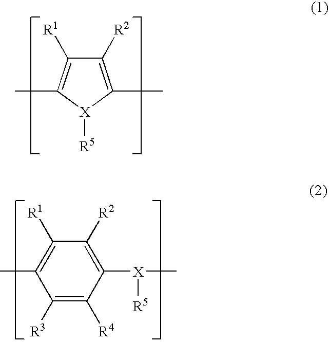
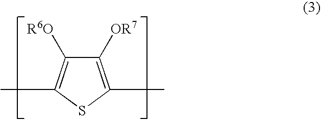
The present invention solves the problem of low-temperature production of a solid electrolytic capacitor with a lower ESR and higher current-passing ability. The invention uses a metal powder with specific properties for the main component of the metal powder-containing paste layer used in the electrically conducting layer of the capacitor. The electrically conducting metal powder can be selected from a variety of options, such as silver, copper, aluminum, nickel, and a coated powder with silver jacket. The thickness of the electrically conducting paste layer should be at least 10 μm. The invention also provides a solid electrolytic capacitor with improved performance using a semiconductor layer and an organic semiconductor layer. The polymer used in the capacitor can be a polymer containing a repeating unit represented by formulas (I) and (II).
Problems solved by technology
In recent years, there has been rising demand of electric devices for a solid electrolytic capacitor having a lower ESR and allowing an ever-larger current to pass, but it has been difficult to satisfy the demand.
Furthermore, the above-described method of producing a solid electrolytic capacitor by using an electrically conducting paste is complicated and a more economical method has been demanded.
Method used
View moreImage
Smart ImageViewing Examples


Examples
examples 13 to 16
[0085]A plurality of chip solid electrolytic capacitors were produced in the same manner as in Example 3 except that the niobium sintered body of Example 3 was replaced by a niobium monoxide sintered body (sintering temperature: 1,4800° C., CV: 180,000 μF·V / g, mass: 0.065 g) produced by sintering a niobium monoxide powder having an average particle size of 120 μm resulting from granulating a niobium monoxide powder (particle size: 0.5 μm) obtained by reducing diniobium pentoxide, and the attaching amount of silver paste was varied to sequentially change the thickness of the silver paste layer.
Login to View More PUM
| Property | Measurement | Unit |
|---|---|---|
| tap density | aaaaa | aaaaa |
| thickness | aaaaa | aaaaa |
| pore depth | aaaaa | aaaaa |
Abstract
The present invention relates to a solid electrolytic capacitor with low ESR obtained by stacking a dielectric layer on a surface of an anode body comprising a valve-acting metal or an electrically conducting oxide, further sequentially stacking a semiconductor layer and an electrically conducting layer on the dielectric layer to prepare a solid electrolytic capacitor element, and molding it with a jacket material, the electrically conducting layer having an electrically conducting paste layer mainly comprising an electrically conducting metal powder and resin, wherein the tap density of the electrically conducting metal powder is 4 g / cm3 or more, and an electronic circuit and an electronic device using the solid electrolytic capacitor.
Description
CROSS-REFERENCE TO RELATED APPLICATIONS[0001]This is an application filed pursuant to 35 U.S.C. Section 111(a) with claiming the benefit of U.S. provisional application Ser. No. 60 / 553,529 filed Mar. 17, 2004 under the provision of 35 U.S.C. 111(b), pursuant to 35 U.S.C. Section 119(e)(1).TECHNICAL FIELD[0002]The present invention relates to a solid electrolytic capacitor with low ESR, and use thereof.BACKGROUND ART[0003]The capacitor utilized for central processing unit (CPU) for personal computers and the like is required to have high capacitance and low ESR (equivalent series resistance) so as to suppress the fluctuation of voltage and reduce the heat generation at the passing of a high ripple current.[0004]Generally, an aluminum or tantalum solid electrolytic capacitor is used.[0005]The solid electrolytic capacitor is produced by stacking a dielectric layer on a surface of an anode body comprising a valve-acting metal or an electrically conducting oxide, further sequentially sta...
Claims
Login to View More Application Information
Patent Timeline
 Patent Type & AuthorityPatents(United States)
IPC IPC(8): H01G9/04H01G9/02H01G9/025
CPCH01G9/025H01G9/0425H01G9/07H01G9/028
InventorNAITO, KAZUMITAMURA, KATUTOSHI
OwnerMURATA MFG CO LTD