White OLEDs with a color-compensated electroluminescent unit

a color-compensated, electroluminescent unit technology, applied in the direction of discharge tube luminescnet screens, natural mineral layered products, etc., can solve the problems of difficult to achieve a wide emission with a balanced intensity from red, green, and only one lel, so as to achieve a wide range of emission and reduce the drive voltage , the effect of fewer fabrication steps

Active Publication Date: 2009-07-14
GLOBAL OLED TECH
View PDF28 Cites 36 Cited by
  • Summary
  • Abstract
  • Description
  • Claims
  • Application Information

AI Technical Summary

Benefits of technology

[0010]It is an object of the present invention to make white OLEDs having improved white color.
[0012]It is another object of the present invention to make white OLEDs with high luminance efficiency and high brightness.
[0013]It is another object of the present invention to make white OLEDs with improved lifetime.
[0014]It is yet another object of the present invention to make white OLEDs with improved color stability.
[0015]It is a further object of the present invention to make tandem white OLEDs with relatively simple fabrication steps.

Problems solved by technology

However, a white OLED with only one LEL will have neither a wide enough emission covering the whole visible spectrum, nor will it have a high luminance efficiency.
However, it is difficult to achieve a wide emission with a balanced intensity from red, green, and blue colors because a white OLED having two LELs typically has only two intensive emission peaks.
A white OLED having three LELs of different color was also proposed but it is still difficult to achieve a wide emission from the device because the most intensive light typically comes from the LEL with a dopant having the narrowest optical band gap and the emission spectrum shifts with different drive conditions.
As a result, in order to achieve a comparable emission intensity of the specific primary color, the corresponding white OLED pixel has to be driven under higher current density causing higher power consumption and a shorter lifetime.
While this permits for improved color emission and a larger emission area compared to conventional full-color OLEDs, the overall construction of the OLED is complex, requiring transparent electrodes, additional bus lines for providing electrical power, as well as a separate power source for each of the stacked OLED units.
units. While color emission and luminance efficiency can be improved, this tandem white OLED cannot be made with less than three EL units, requiring that the drive voltage be at least 3 times as high as that of a convention

Method used


Image

  • White OLEDs with a color-compensated electroluminescent unit
  • White OLEDs with a color-compensated electroluminescent unit
  • White OLEDs with a color-compensated electroluminescent unit

Examples


example 1

Comparative

[0081]The preparation of a comparative white OLED is as follows: A˜1.1 mm thick glass substrate coated with a transparent indium-tin-oxide (ITO) conductive layer was cleaned and dried using a commercial glass scrubber tool. The thickness of ITO is about 42 nm and the sheet resistance of the ITO is about 68 Ω / square. The ITO surface was subsequently treated with oxidative plasma to condition the surface as an anode. A layer of CFx, 1 nm thick, was deposited on the clean ITO surface as the hole-injecting layer by decomposing CHF3 gas in an RF plasma treatment chamber. The substrate was then transferred into a vacuum deposition chamber for deposition of all other layers on top of the substrate. The following layers were deposited in the following sequence by evaporation from a heated boat under a vacuum of approximately 10−6 Torr:

1. EL Unit:

[0082]a) an HTL, about 90 nm thick, including “4,4′-bis[N-(1-naphthyl)-N-phenylamino]biphenyl” (NPB);[0083]b) a first LEL, 20 nm thick, ...

example 2

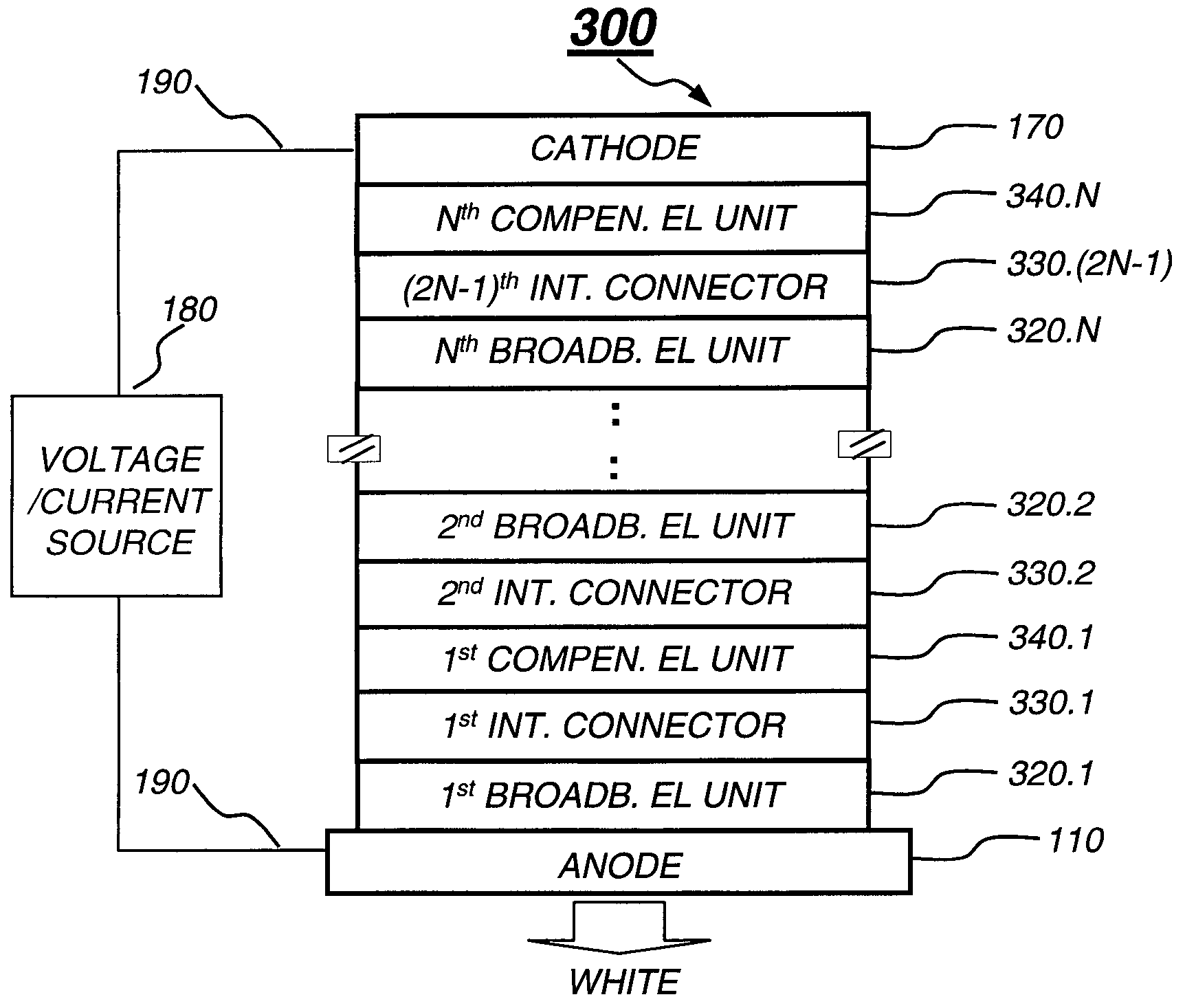
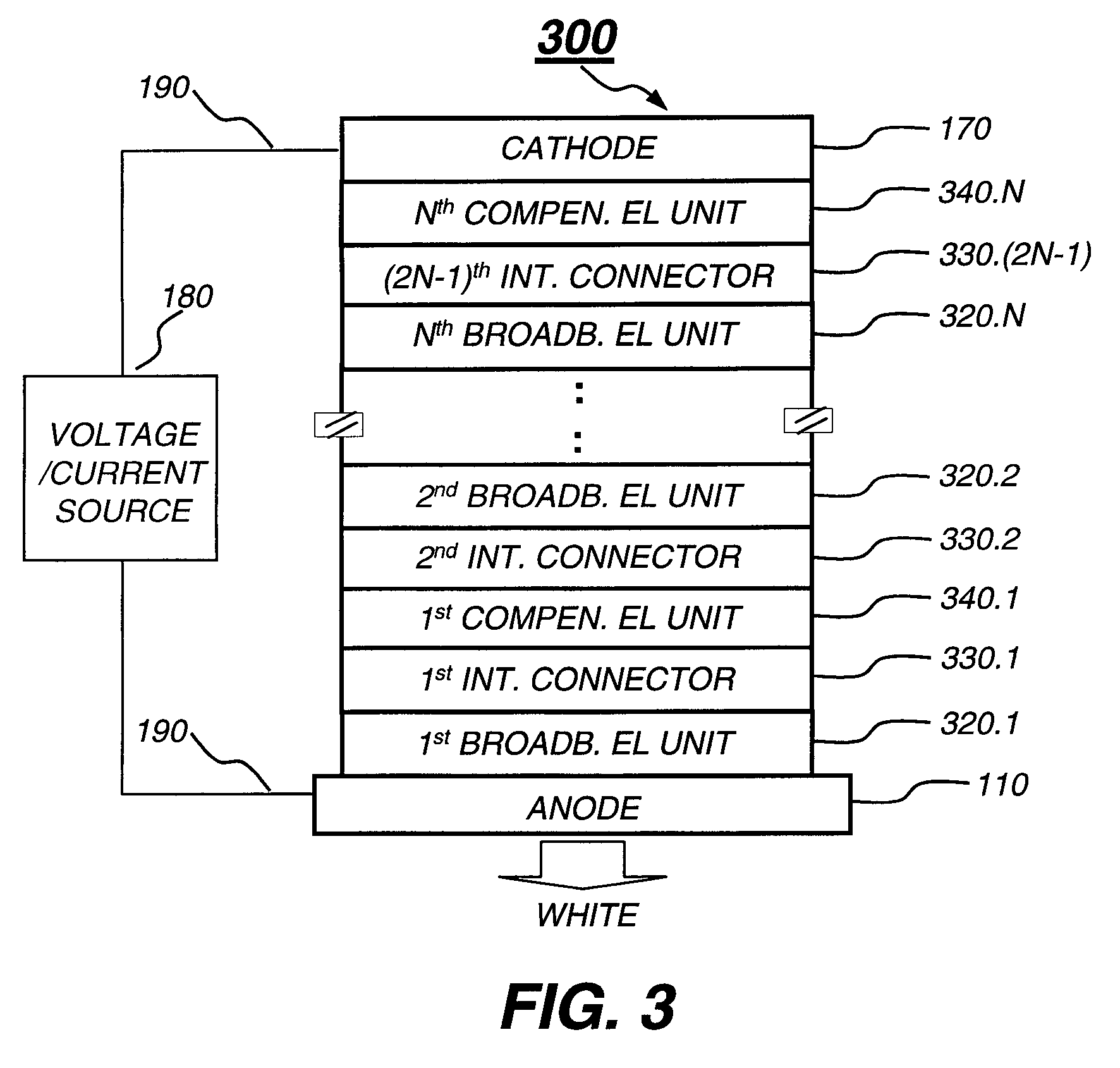
[0088]A tandem white OLED was constructed in accordance with the present invention as described in FIG. 4. The fabrication methods used in Example 2 are similar to those used in Example 1, and the deposited layer structure is:

1. 1st EL Unit (1st Broadband EL Unit):

[0089]a) an HTL, about 30 nm thick, including NPB;[0090]b) a first LEL, 30 nm thick, including 70 vol. % NPB, 29.5 vol. % rubrene, and 0.5 vol. % “5,10,15,20-tetraphenyl-bisbenz[5,6]indeno[1,2,3-cd: 1′,2′,3′-1 m]perylene” (red emitting layer);[0091]c) a second LEL, 40 nm thick, including 85 vol. % “2-(1,1-dimethyethyl)-9,10-di-2-naphthalenyl anthracene” (TBADN), about 13.5 vol. % NPB, and 1.5 vol. % “2,5,8,11-tetra-t-butylperylene (TBP)” (blue emitting layer); and[0092]d) an ETL, 10 nm thick, including Alq.

2. 1st Intermediate Connector:[0093]a) an n-type doped organic layer, 10 nm thick, including Alq doped with about 1.2 vol. % lithium; and[0094]b) a metal compound layer, 2 nm thick, including WO3.

3. 2nd EL Unit (1st Colo...


PUM

PropertyMeasurementUnit
work functionaaaaaaaaaa
thicknessaaaaaaaaaa
thickaaaaaaaaaa

Abstract

A tandem white OLED includes an anode; a cathode; at least one broadband electroluminescent unit disposed between the anode and the cathode, wherein the broadband electroluminescent unit includes at least one light-emitting layer and produces at least one color component having an intensity less than desired; at least one color-compensating electroluminescent unit disposed between the anode and the cathode, wherein the color-compensating electroluminescent unit is selected to produce the at least one color component and to increase the color component intensity; and an intermediate connector disposed between each adjacent electroluminescent unit, wherein the intermediate connector has no direct connection to an external power source.

Description

CROSS REFERENCE TO RELATED APPLICATIONS[0001]Reference is made to commonly assigned U.S. patent application Ser. No. 10 / 437,195 filed May 13, 2003 by Liao et al., entitled “Cascaded Organic Electroluminescent Device Having Connecting Units with n-Type and p-Type Organic Layers”; U.S. patent application Ser. No. 10 / 857,516 filed May 28, 2004 by Liang-Sheng Liao et al., entitled “Tandem OLED Having Stable Intermediate Connectors”; U.S. patent application Ser. No. 10 / 882,834 filed Jul. 1, 2004 by Tukaram K. Hatwar et al., entitled “High Performance White Light-Emitting OLED Device”; and U.S. patent application Ser. No. 10 / 922,606 filed Aug. 20, 2004 by Liang-Sheng Liao et al., entitled “White OLED Having Multiple White Electroluminescence Units”, the disclosures of which are herein incorporated by reference.FIELD OF INVENTION[0002]The present invention relates to providing a plurality of organic electroluminescent (EL) units to form a tandem white organic electroluminescent device.BACK...

Claims


Application Information

Patent Timeline
Patent Type & Authority Patents(United States)
IPC IPC(8): H05B33/14H05B33/00H01J1/62H01L51/50
CPCH01L51/5036H01L51/5278H01L51/0052H01L51/0053H01L51/0054Y10S428/917H01L51/0081H10K85/621H10K85/622H10K85/615H10K85/324H10K50/125H10K50/19H01L21/0455H10K59/10
Inventor LIAO, LIANG-SHENGHATWAR, TUKARAM K.KLUBEK, KEVIN P.COMFORT, DUSTIN L.TANG, CHING W.
Owner GLOBAL OLED TECH
Why Eureka
Try Eureka