Interstitially strengthened high carbon and high nitrogen austenitic alloys, oilfield apparatus comprising same, and methods of making and using same

a technology of austenitic alloys and interstitial strengthening, which is applied in the field of ferrous alloys, can solve the problems of reducing the overall performance of the alloy in corrosive environments, corrosion resistance, and essentially commercially available high-nitrogen steels, and achieves high strength, low raw material cost, and high resistance in corrosive environments

Inactive Publication Date: 2010-02-09
SCHLUMBERGER TECH CORP
View PDF19 Cites 4 Cited by
  • Summary
  • Abstract
  • Description
  • Claims
  • Application Information

AI Technical Summary

Benefits of technology

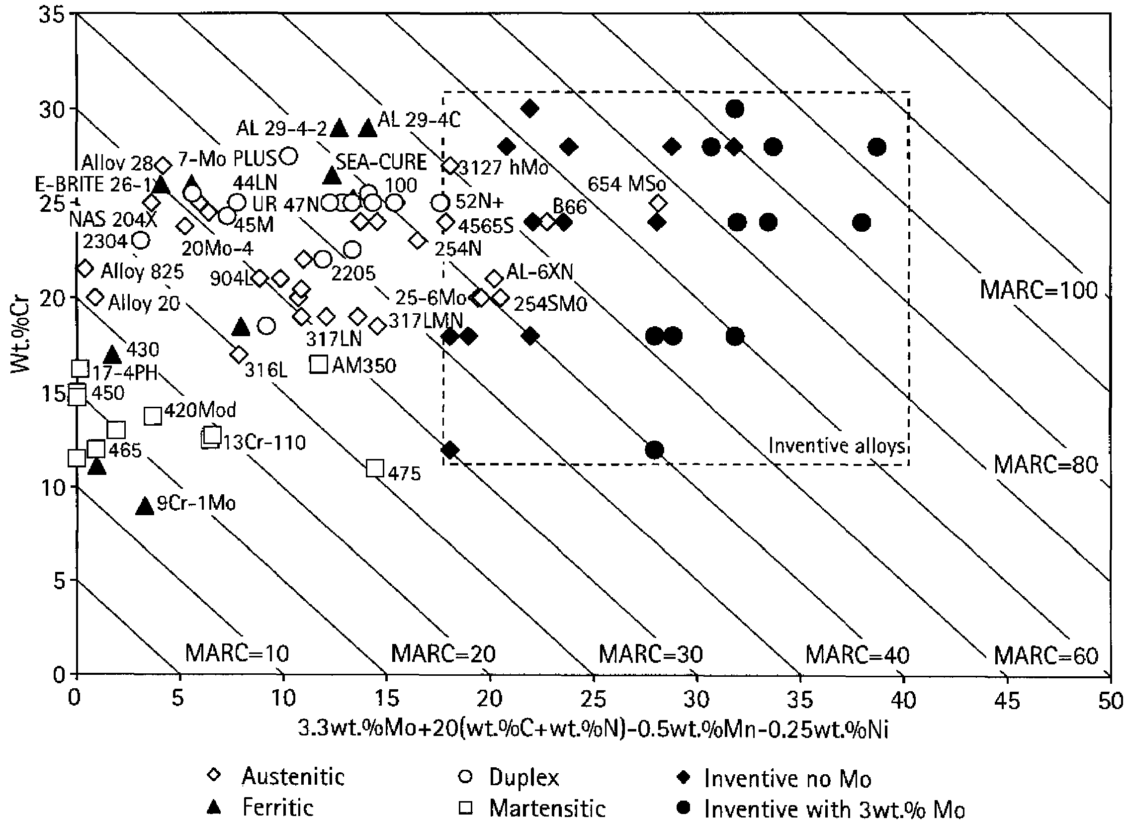
[0021]Ferrous alloys of the invention are relatively low-cost because of the substitution of austenite (γ) stabilizing metals by nitrogen (N). Contents of carbon (C) and nitrogen (N) are such that the equilibrium phases of the inventive ferrous alloys are predominantly if not solely austenitic; occasionally carbide, nitride, carbonitride hard phase may form but may be dissolve through heat treatments. In the inventive alloys, the absence of delta ferrite (δ) upon solidification is important to prevent porosity (voids), and provides high levels of soluble nitrogen (N). The selection and content of alloying elements is thus not only dictated by the corrosion resistance, but also by the high interstitial carbon (C) and nitrogen (N) needed by the austenitic microstructure to exhibit a high corrosion resistance and a considerable strength.
[0022]In certain embodiments of the inventive alloys, sufficient chromium (Cr) may be present in order to render the alloy stainless as well as increase the nitrogen (N) solubility in both the liquid and austenite (γ), while manganese (Mn) is necessary to prevent delta ferrite (δ) formation upon solidification and enhance the nitrogen (N) solubility in both the liquid and the austenite (γ). This is in stark contrast with the alloys listed in Table 1, wherein manganese (Mn) is absent and carbon (C) and nitrogen (N) are neither combined nor used significantly. For high corrosion resistance and high nitrogen (N) solubility, exemplary embodiments of the inventive ferrous alloys comprise from about 12 wt. % to 30 wt. % chromium (Cr). Certain other embodiments of the inventive ferrous alloys may comprise from about 8 wt. % to about 30 wt. % manganese (Mn); like chromium (Cr), an alloying element utilized to boost nitrogen (N) solubility over 0.4 wt. %. Other embodiments of the inventive ferrous alloys may comprise one or more of nickel (Ni) and cobalt (Co) wherein the total ranges from about 1.0 wt. % to approximately 4.0 wt. %. Other embodiments of the inventive ferrous alloys may comprise from about 0.1 wt. % to about 2.0 wt. % silicon (Si); an alloying element used to deoxidize and free the alloy from oxygen (O) interstitials. Yet other embodiments of the inventive ferrous alloys may comprise one or more of molybdenum (Mo), titanium (Ti), niobium (Nb), zirconium (Zr), vanadium (V), and tungsten (W), wherein the total of these is less than or equal to about 0.5 wt. % to provide strong substitutional solid solution but avoid significant carbides and other phases from forming, unless desired. Other embodiments of the inventive ferrous alloys may comprise aluminum (Al) up to about 0.5 wt. %. In all embodiments, sulfur (S) and phosphorous (P) must be practically absent so as to enable large solubility for carbon (C) and nitrogen (N), prevent cracking upon during solidification, prevent the formation of deleterious phases such as sulfides and phosphides, and prevent embrittlement (e.g. ductility loss).

Problems solved by technology

In contrast with numerous grades of stainless steels, the high-nitrogen steels are essentially commercially unavailable.
These minor phases may include other ferrous phases such as ferrite (α), martensite (with no restrictions to the various types of martensite), intermetallic phases or compounds of metals and nitrogen (N), carbon (C), or other non-metallic element, even though these phases will generally reduce the overall performance of the alloy in corrosive environments; that is its corrosion resistance.
Of all the properties of the commercial alloys of Table 1, their strength is often insufficient for downhole applications and thus constitutes a major disadvantage that prevents them from rivaling the nickel alloys used today in downhole applications, and, when their strength is adequate, these alloys are considerably pricy, thus establishing another limit to their use.
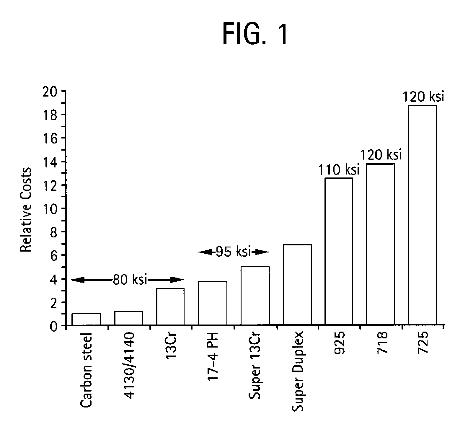
However, in part related to their excellent toughness, the austenitic alloys are promising for use in oil and gas applications, especially in sour environments, whereas the martensitic steels are inherently limited by their poor resistance against hydrogen embrittlement (including sulfide stress cracking). FIG. 1 is a histogram chart for the major alloys currently used in oilfield subsurface applications (including completion equipment) showing price estimates per pounds (normalized to that of carbon steels) along with the alloy recommended tensile strengths.
However, as noted by some of the same inventors in DE 196 07 828 A1, these articles have modest fatigue strength—at best 375 MPa (55 ksi)—and this fatigue strength is significantly lower in an aggressive environment such as saline environments.
However, one disadvantage thereof is a low nitrogen (N) solubility that is attributable to the alloy composition, which is why melting and solidification have to be carried out under pressure, or still more burdensome powder metallurgical production methods must be utilized.
As described in this document, corrosion is a complex type of damage and the exact behavior of various alloys cannot be precisely predicted in different oilfield environments.

Method used


Image

  • Interstitially strengthened high carbon and high nitrogen austenitic alloys, oilfield apparatus comprising same, and methods of making and using same
  • Interstitially strengthened high carbon and high nitrogen austenitic alloys, oilfield apparatus comprising same, and methods of making and using same
  • Interstitially strengthened high carbon and high nitrogen austenitic alloys, oilfield apparatus comprising same, and methods of making and using same

Examples


Embodiment Construction

[0054]In the following description, numerous details are set forth to provide an understanding of the present invention. However, it will be understood by those skilled in the art that the present invention may be practiced without these details and that numerous variations or modifications from the described embodiments may be possible.

[0055]Described herein are inventive ferrous alloy compositions, shaped articles of manufacture (apparatus) employing one or more of the inventive ferrous alloys, and methods of making and using the apparatus, particularly as oilfield elements. Oilfield applications may include exploration, drilling, and production activities including producing water wherein oil or gaseous hydrocarbons are or were expected. As used herein the term “oilfield” includes land based (surface and sub-surface) and sub-seabed applications, and in certain instances seawater applications, such as when exploration, drilling, or production equipment is deployed through a water ...


PUM

PropertyMeasurementUnit
temperatureaaaaaaaaaa
pressureaaaaaaaaaa
temperatureaaaaaaaaaa

Abstract

Novel carbon-plus-nitrogen corrosion-resistant ferrous and austenitic alloys, apparatus incorporating an inventive alloy, and methods of making and using the apparatus are described. The corrosion-resistant ferrous and austenitic alloys comprise no greater than about 4 wt. % nickel, are characterized by a strength greater than about 700 MPa (100 ksi), and, when being essentially free of molybdenum (<0.3 wt. %), have minimum Pitting Resistance Equivalence (PRE) numbers of 20 and minimum Measure of Alloying for Corrosion Resistance numbers (MARC) of 30 because of the use of both carbon and nitrogen. The ferrous and austenitic alloys are particularly formulated for use in oilfield operations, especially sour oil and gas wells and reservoirs. This abstract allows a searcher or other reader to quickly ascertain the subject matter of the disclosure. It will not be used to interpret or limit the scope or meaning of the claims.

Description

BACKGROUND OF THE INVENTION[0001]1. Field of Invention[0002]The present invention relates to ferrous alloys that possess high-strength, good corrosion resistance in environments such as oilfield exploration, production, and testing, and more specifically to carbon-plus-nitrogen austenitic alloys that are interstitially strengthened, apparatus comprising these novel alloys, and methods of making and using same.[0003]2. Related Art[0004]The art of fabricating corrosion resistant ferrous alloys (including stainless steels and the so-called “high-nitrogen steels”) is well-documented (see Kamachi Mudali, U., Baldel Raj, “High Nitrogen Steels and Stainless Steels-Manufacturing, Properties and Applications”, Narosa Publishing House, ASM International, New Delhi (2004), hereinafter referred to as “Kamachi”). The use of nitrogen (N) as an alloying element is also well reported; however nitrogen (N) in high contents (or concentrations; in this document the two words are used interchangeably w...

Claims


Application Information

Patent Timeline
Patent Type & Authority Patents(United States)
IPC IPC(8): C21D1/74C22C33/04C22C38/00C22C38/58
CPCC22C38/001C22C38/06C22C38/58C22C38/44Y10T428/12951
Inventor MARYA, MANUELBHAVSAR, RASHMI
Owner SCHLUMBERGER TECH CORP
Why Eureka
Try Eureka