Process for hydrogen production via integrated processing of landfill gas and biomass

a technology of landfill gas and biomass, which is applied in the direction of combustible gas production, metal/metal-oxide/metal-hydroxide catalysts, chemical production, etc., can solve the problems of reducing the overall efficiency of converting lfg to hydrogen by this route, reducing the environmental footprint of the technology, and simplifying the technological chain of the process.

Inactive Publication Date: 2010-04-06
UNIV OF CENT FLORIDA RES FOUND INC
View PDF8 Cites 29 Cited by
  • Summary
  • Abstract
  • Description
  • Claims
  • Application Information

AI Technical Summary

Benefits of technology

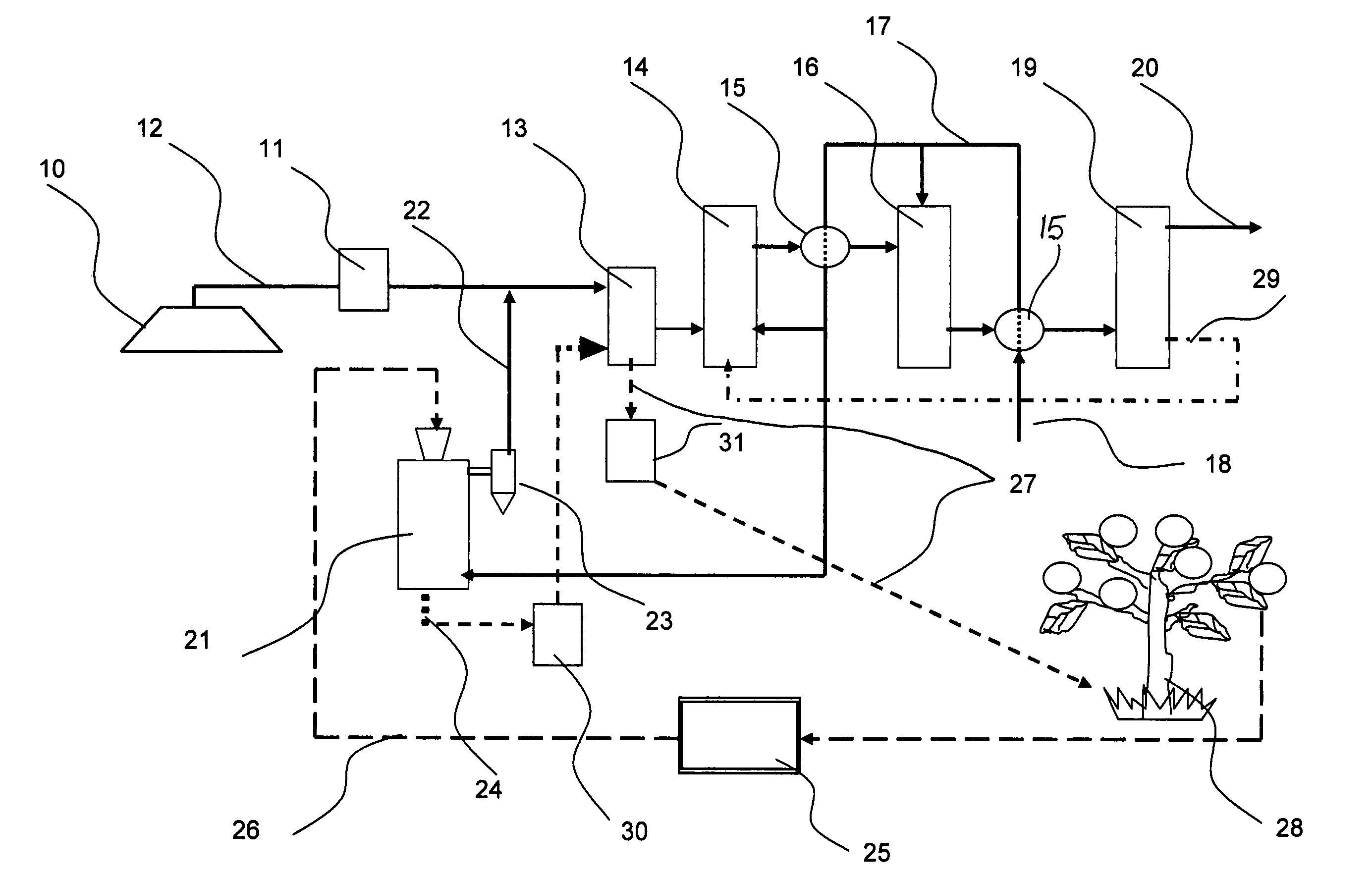
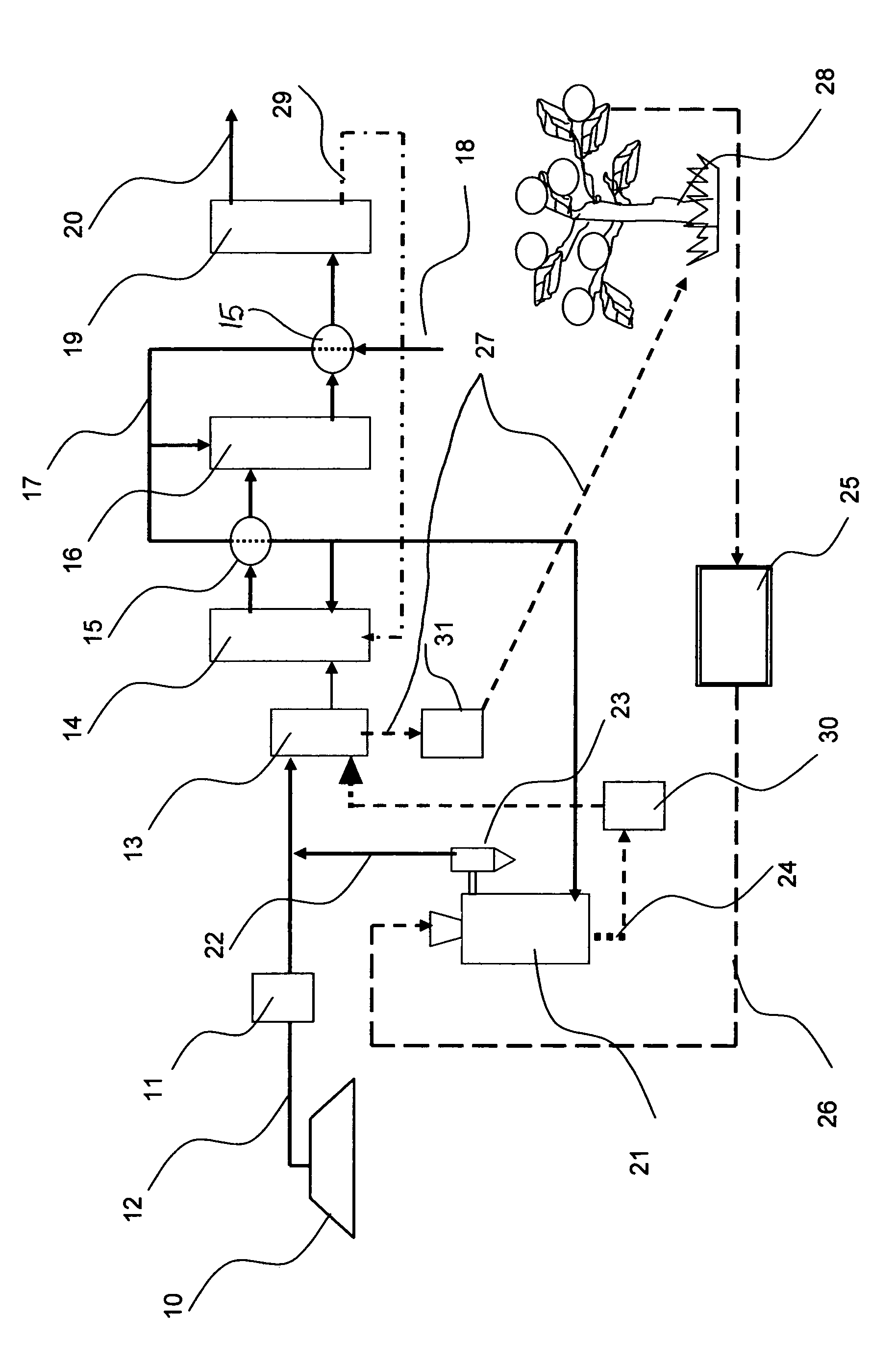
[0023]A second objective of the invention is to integrate the processing of two types of feedstocks, such as a gas, LFG and a solid, biomass, in order to simplify the technological chain of the process.
[0024]A third objective of the invention is to accomplish a close

Problems solved by technology

However, fossil-based fuels are considered finite, and are the main source of air pollution, producing CO2, NOx, SOx and other pollutants that cause considerable damage to the environment.
However, the overall efficiency for converting LFG to hydrogen via this route is less than 20% and it is unlikely to be of practical importance.
Thus, the technical approach according to the methane extraction method is complex, multi-step and energy intensive.
In many cases, this method may not be economically and/or environmentally advantageous, especially when the resources are not large enough or the sources are located in remote areas.
The technical difficulties associated with the direct catalytic reformation of LFG or biogas stem mainly from two facto

Method used


Image

  • Process for hydrogen production via integrated processing of landfill gas and biomass
  • Process for hydrogen production via integrated processing of landfill gas and biomass

Examples


example 1

[0070]Catalytic reforming of the gaseous mixture CH4—56.9 vol. % and CO2—43.1 vol. % (molar ratio of CH4 / CO2=1.3) was conducted in this experiment. This gaseous mixture mimics that of LFG from the landfill site in Cocoa, Fla. For the sake of simplicity, N2, O2 and minor ingredients were not included in the tested feedstock. The reforming reaction was conducted in a quartz reactor with OD=12 mm using 0.5 g of Ru (0.5 wt. %) / Al2O3 catalyst at 850° C. and atmospheric pressure. After about one hour from the start of the reaction the steady state process was established with the production of the gaseous product of the following average composition (vol. %): H2—45.4, CO—44.8, CH4—8.9, CO2—0.9. Within the detection limits of an analyzer used, no carbon was detected on the surface of Ru-catalyst during 5 hrs with the average CO2 conversion during the same period measured at 98.9%. Thus, Ru-catalyst demonstrates both high activity and selectivity for CH—CO2 reforming reaction; hence, a very...

example 2

[0071]The experimental conditions were similar to those of the Example 1, except NiO(1-15 wt. %) / Al2O3 was used as a catalyst. Initially, the hydrogen concentration in the effluent gas was in excess of 50 vol. %, but the reaction was not sustainable and hydrogen concentration steadily decreased during the experiment. The amount of carbon accumulated on the catalyst surface after 5 hours corresponded to a methane-to-carbon conversion yield of 15.3 mol. %. After the reaction, the catalyst completely disintegrated from pellets into a fine powder. These experimental observations evidence a major role played by methane decomposition reaction in the overall reforming process. Carbon produced by methane decomposition reaction blocks catalytic active sites causing gradual deactivation of the catalyst. Disintegration of Ni-catalyst can be explained by the growth of carbon particles inside the catalyst pores. This experiments points to high catalytic activity and low selectivity of Ni-catalys...

example 3

[0072]The experimental condition of the reaction and the catalyst used were similar to those of the Example 2, except steam was added to the reagents in order to prevent carbon lay down on the NiO / Al2O3 catalyst surface. Steam was added to methane-CO2 mixture in the amount equimolar to the quantity of methane. Thus the components of the feedstock were as follows: CH4:H2O:CO2: =1.3:1.3:1 (molar). The addition of steam allowed sustainable reaction during 12 hrs of operation. The average concentrations of hydrogen and CO in the effluent gas were 58 and 34.5 vol. %, respectively. The H2 / CO ratio in the presence of steam increased appreciably compared to the experiment of the Example 2, where no steam was added (from H2 / CO=1.2 to 1.7). Carbon dioxide concentration in the product gas was also increased. No carbon deposits were detected on the catalyst surface after the experiment. There were no signs of Ni-catalyst disintegration after the reforming experiments involving steam.


PUM

PropertyMeasurementUnit
Temperatureaaaaaaaaaa
Pressureaaaaaaaaaa

Abstract

Hydrogen production is provided via integrated closed-loop processing of landfill gas (LFG) and solid biomass feedstocks such as various agricultural wastes with minimal environmental impact. LFG is purified of harmful contaminants over a bed of activated charcoal (AC) and is catalytically reformed to synthesis gas, which is further processed to pure hydrogen via CO-shift and pressure-swing adsorption stages. Biomass is gasified in the presence of steam with production of a producer gas and AC. The producer gas is mixed with LFG and is processed to hydrogen as described above. High-surface area AC produced in the gasifier is used for the purification of both LFG and producer gas. An integrated processing of LFG and biomass offers a number of advantages such as a high overall energy efficiency, feedstock flexibility, substantial reduction in greenhouse gas emissions and production of value-added product-biocarbon that can be used as a soil enhancer.

Description

[0001]The present invention is related to hydrogen production methods, and, in particular, to a process for production of hydrogen via integrated processing of biomass-derived feedstocks such as landfill gas, biogas, wood, agricultural wastes, animal wastes, and certain types of municipal solid waste, e.g., urban wood waste, paper, biological and vegetative waste.BACKGROUND AND PRIOR ART[0002]Hydrogen is universally considered a fuel of the future due to environmental advantages over conventional (i.e., fossil-based) fuels.[0003]As reported by N. Z. Muradov and T. N. Veziroglu in “From hydrocarbon to hydrogen-carbon to hydrogen economy”International Journal of Hydrogen Energy 30 (2005)225-237 in the near- to medium-term, hydrogen production is likely to continue to rely on fossil fuels, that are still abundantly available, relatively low cost and with an existing infrastructure for delivery and distribution. However, fossil-based fuels are considered finite, and are the main source ...

Claims


Application Information

Patent Timeline
IPC IPC(8): B01D53/02
CPCC10K3/04B01D53/75C01B3/323C01B3/38C01B3/48C01B3/506C01B3/56C10J3/00C10L3/08C10L3/10C10L5/44C10K3/02B01D53/02B01D2253/102B01D2253/108B01D2256/16B01D2257/20B01D2257/30B01D2257/304B01D2257/406B01D2257/504B01D2257/80B01D2258/05B01J23/462B01J23/755C01B2203/0205C01B2203/0238C01B2203/0283C01B2203/043C01B2203/046C01B2203/0465C01B2203/0475C01B2203/0485C01B2203/1047C01B2203/1082C01B2203/1241C01B2203/1258C10J2300/0916C10J2300/0973C10J2300/16C10J2300/1681C10J2300/1807Y02C20/20Y02E50/10Y02E50/30Y02E50/346B01D53/047Y02P20/145Y02P20/151Y02P20/52
Inventor MURADOV, NAZIM Z.SMITH, FRANKLYNTABATABAIE-RAISSI, ALI
Owner UNIV OF CENT FLORIDA RES FOUND INC
Why Eureka
Try Eureka