Prediction of shallow drilling hazards using seismic refraction data

a technology of seismic refraction and shallow drilling, applied in the direction of scientific instruments, measurement devices, instruments, etc., to achieve the effect of increasing spatial sampling

Inactive Publication Date: 2010-09-14
SAUDI ARABIAN OIL CO
View PDF24 Cites 33 Cited by
  • Summary
  • Abstract
  • Description
  • Claims
  • Application Information

AI Technical Summary

Benefits of technology

[0041]The method of the present invention departs from the conventional use of reflection seismic data and instead employs the refraction data that is recorded but conventionally discarded. This greatly enhances spatial sampling. The near-surface effects on each refracted wave arrival are preferably addressed independently, and following additional processing steps, utilizing commercially available software, each refractor is visualized for the presence of karsts and other potentially hazardous features.
[0044]The method of the invention has the advantages of enhancing the economy and safety of drilling in hydrocarbon exploration and recovery by using elements of pre-existing seismic data that are conventionally discarded or muted, processing it in a novel manner and presenting it for interpretation in a form that facilitates identification of karsts and other shallow drilling hazards.
[0052]The time image of each refractor will normally vary spatially with time and if the data quality allows, these surfaces can be flattened to allow the analysis to proceed in the time-slice domain with great effect. The effect of time slice analysis is to actually see the karsted features in a map view as a function of time. In cases of good overall data quality, this analysis mode provides the seismic interpreters and drilling engineers with estimates of the volume of the karsted void. In the case of an unconsolidated collapsed feature the same visual effect has been observed.
[0054]The basic approach to the method of the invention is to analyze each refractor where data from existing wells showed no events in their drilling histories of lost circulation, bit drops, or other such problems. These points will show an undisturbed refractor amplitude / frequency / semblance response. The same analysis is conducted for problem wells in order to establish a simple and straight-forward calibration of the data. The aforementioned semblance volumes are employed for the purpose of confirming observations seen on the amplitude / time minivolumes. In the case of very poor quality data, the semblance volumes can be very useful in the performing analysis.
[0059]As will also be understood by one of ordinary skill in the art, where karsts and unconsolidated collapses are identified in carbonate strata and these hazardous features cannot be avoided due to well spacing constraints, their identification will enable the drilling engineers and staff to plan accordingly to minimize any adverse consequences during drilling operations.
[0060]The process of the invention is advantageously employed to identify large karsts and unconsolidated collapsed features in the subsurface prior to drilling and in the selection of well sites that will obviate or minimize the drilling risks of lost circulation. The invention can also be used to identify very shallow, highly-charged gas zones. Further advantages include providing the drilling engineers with information that enables them to more intelligently and efficiently plan drilling to reduce costs. Finally, by giving the engineers prior warning of these hazards, drilling plans can be altered to enhance the safety profile of drilling through any hazardous zones that cannot otherwise be avoided.

Problems solved by technology

Shallow drilling hazards in carbonate formations are well known to present potential problems in exploration and developmental drilling and can represent a significant risk to the exploitation of hydrocarbons.
If a drill bit and drill string encounter such a karst feature, there is an immediate loss of circulating fluid, and there also can be a bit drop through the void space of the karst.
This can result in the total loss of the well at great expense.
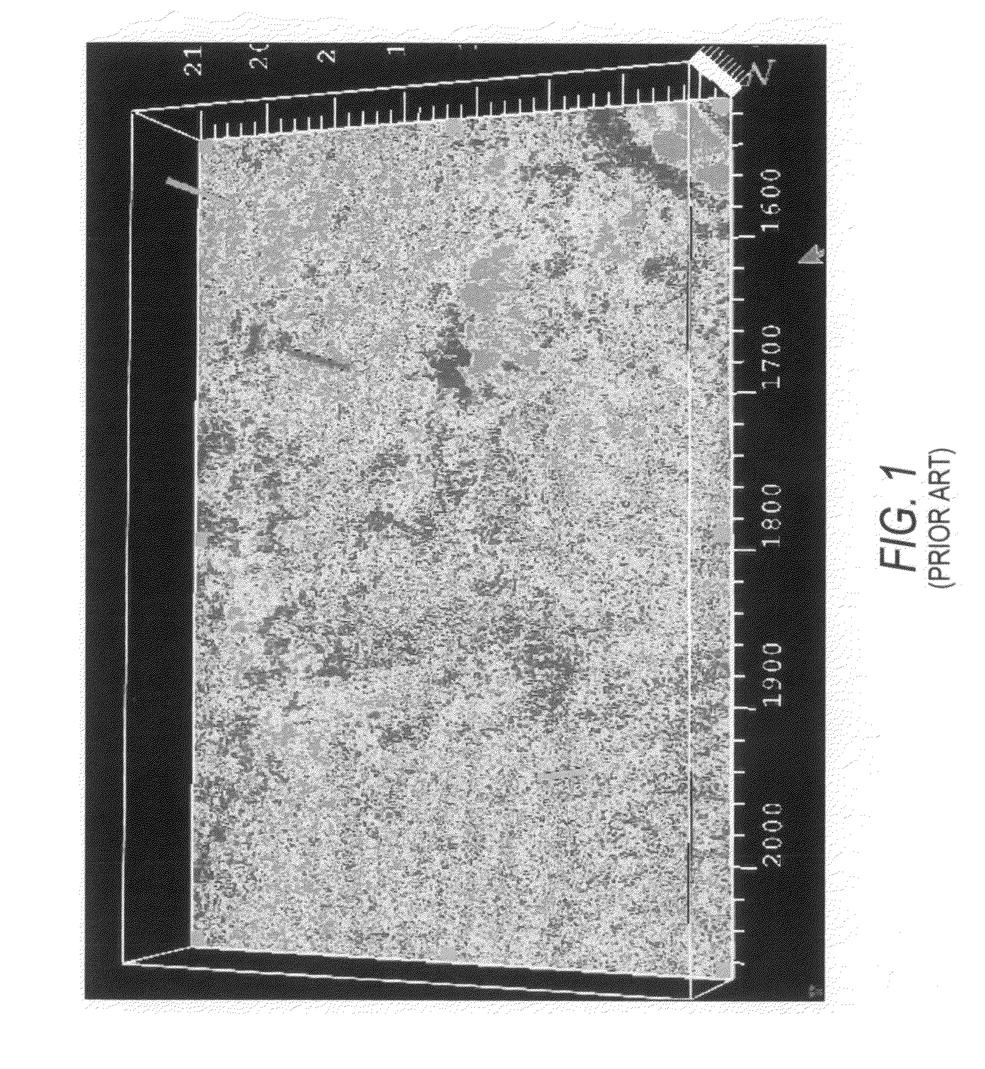
However, such displayed reflection data can show little continuity and so cannot aid in detecting shallow drilling hazards.
These hazards to drilling are very time-consuming to traverse with the drill bit and therefore expensive, and represent a potential danger to drilling crews.
Shallow subsurface voids and the potential for mudslides can endanger the drilling operation.
Further problems can be caused by shipwrecks and other man-made obstructions.
It is also possible for localized zones of natural gas under pressure to exist in very shallow rock strata that would pose both a drilling risk of blowout, as well as a structural risk to the platform.
Should failure occur, it would result in the potential loss of the platform and associated equipment, risk the lives of operating personnel and the loss of millions of dollars in capital investment.
The environmental risks are obvious and significant.
The results have been limited or poor.
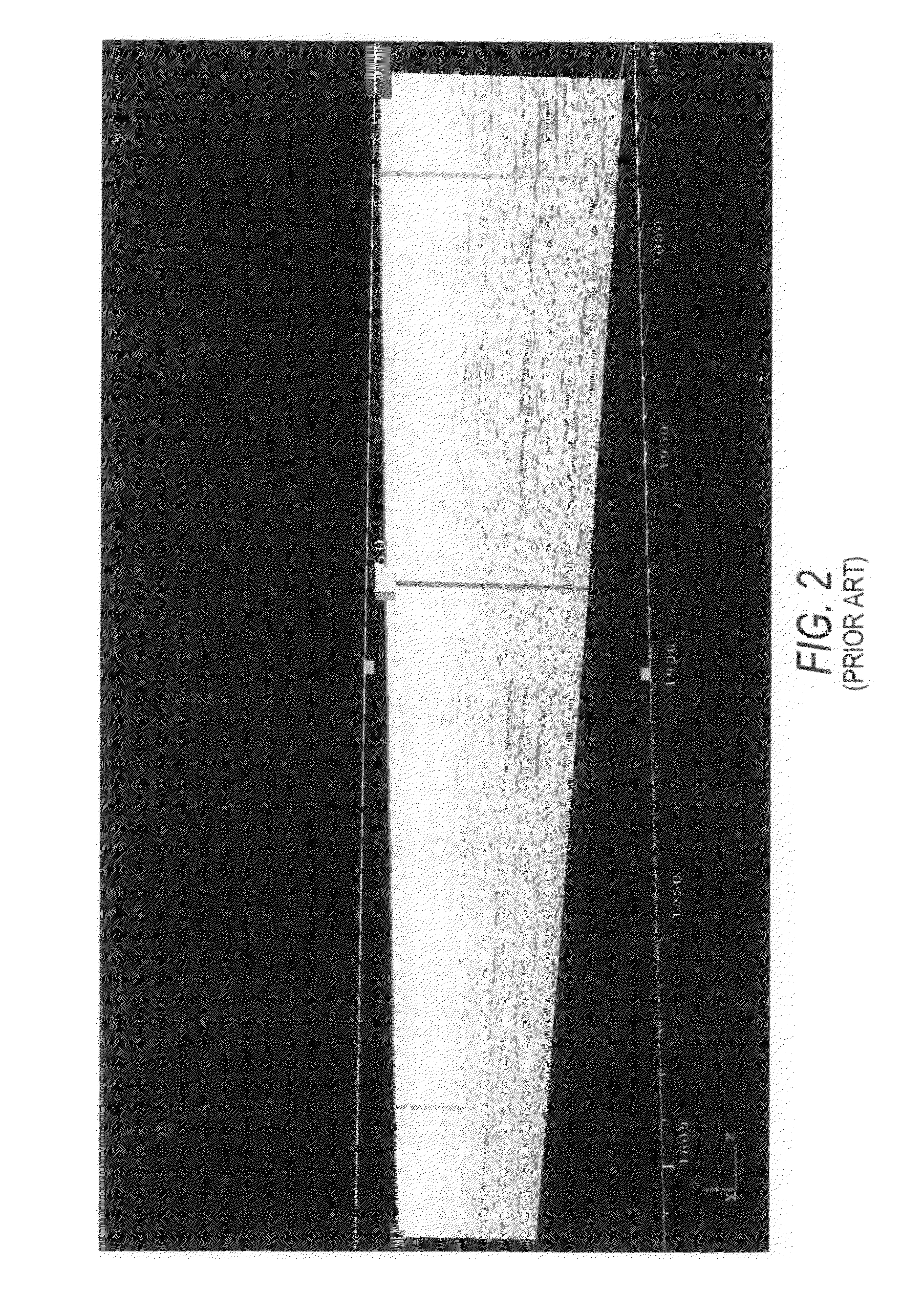
As shown in FIG. 2, the use of conventional seismic reflection data makes it quite impossible to accurately detect any lost circulation, as the noise of the data overwhelms the few traces occupying each bin of data.
While this reflection approach will generally work in a marine environment, it will not work in a high-noise land setting.
The SWD method suffers the drawback that the well is already positioned and drilling is underway, so that the well might be placed in a disadvantageous location, without any practical alternative but to keep drilling.
To date, this method has not been entirely successful.
The reason for the lack of success is the relatively poor sampling of reflections in the very shallow portion of the seismic prestack record.
Absent a very high-resolution survey, which for large drilling programs would be prohibitive in terms of time and cost, there is no apparent method using reflection data that can be improved sufficiently to reliably identify the shallow hazards.
Other proposals and efforts to employ different types of data, such as ground-penetrating radar (GPR) have not proved practical, since penetration into the karsted subsurface is inadequate.
While useful in marine environments, it is not useful in a land setting.
A survey of the patent literature has not revealed a satisfactory solution to the problem.
In the case of larger karsts or as a result of increases in overburden forces, these voids cannot support the weight of the rock strata above and they collapse on themselves.
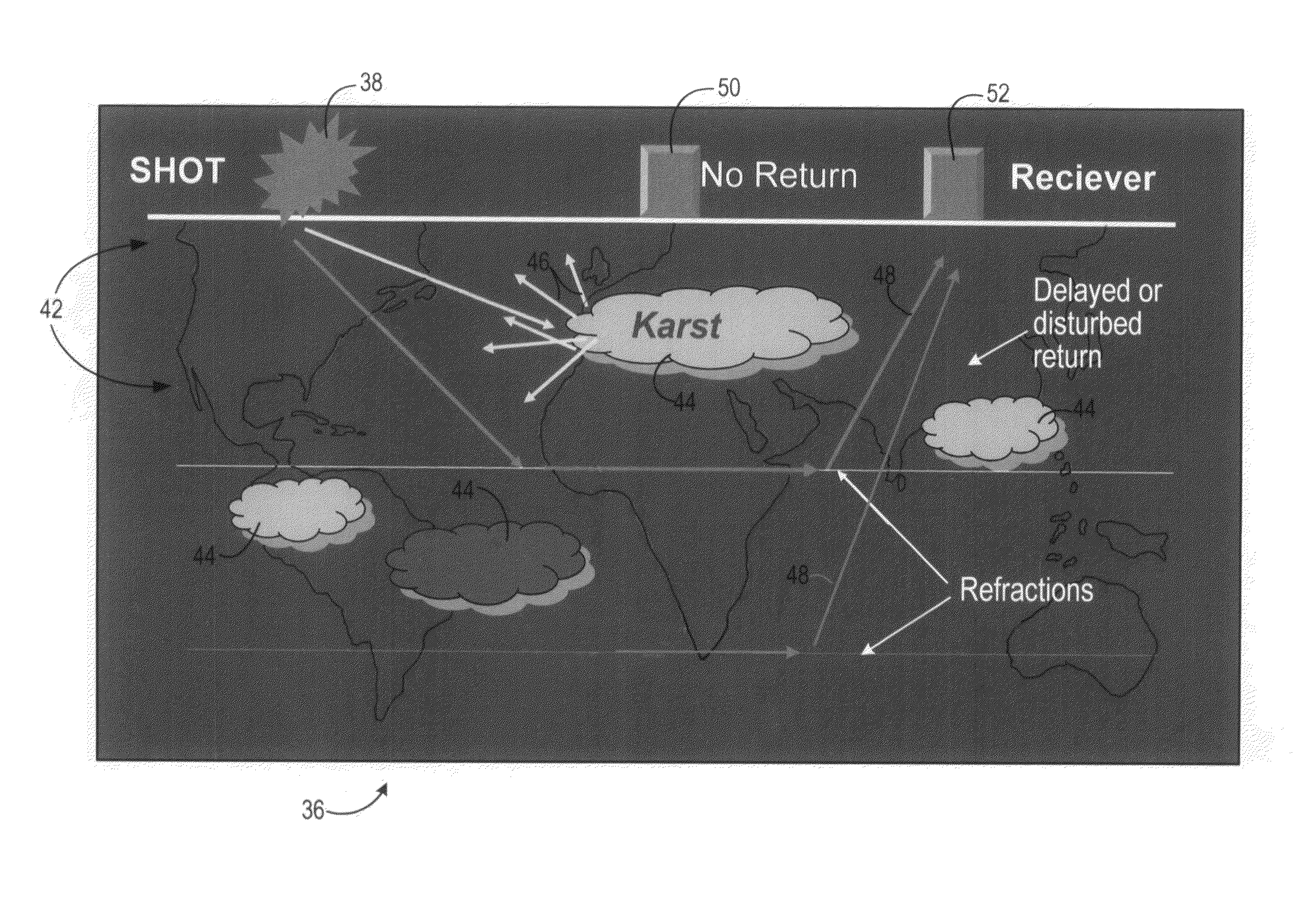
However, when the refracted waveform encounters a void or a heterogeneity in its path, the waveform is disturbed and the resultant amplitude and / or frequency of the wave returned to the receivers is abnormal.
These include, but are not limited to, the loss of the borehole, damage to well structures and equipment, blow-outs, environmental damage and lost drilling fluid circulation.
1. Lost Circulation of Drilling FluidsA. Any sudden loss of the circulating drilling fluid incurs both a monetary loss and an increase in mechanical risk to the equipment.B. If hazards could be identified prior to drilling, the drilling engineers could plan the mud injection program accordingly, which at present they are unable to do. This would result in improved use of material and monetary savings during drilling.
2. Unexpected Drill Bit DropsA. A drop through a void or karst can result in mechanical damage to the drill string and bit.B. The drill string can become stuck in the hole, resulting in the loss of the borehole, in which case the entire well must be redrilled at enormous costs in time and money.
3. Personnel Safety IssuesA. If shallow karsted zones are unknown to drilling personnel, a bit drop can be hazardous to workers on the drilling platform floor.B. Under some circumstances, the rig itself can be damaged if the drill string drops through the drilling floor.
The problem with a land environment, particularly one characterized by shallow carbonates and anhydrites, is that using reflection data will not work as it does in the marine environment.
1. In normally-acquired seismic data, the survey and dimensions are designed for deeper targets which possess commercial potential for hydrocarbon accumulation. These surveys are therefore not sampled adequately in the spatial domain closest to the earth's surface.
2. Reflection land seismic information in the shallow subsurface (above about 1,000 feet) will be muted in the processing of the data. Later, the data recorded at each time sample will be corrected for normal moveout and stacked to suppress random noise. The problem is that, in these shallow zones, there is usually inadequate sampling in offset to statistically cancel out the noise.
These three-dimensional surveys are not designed for shallow target resolution.
However, it has been found that onshore hazard surveys are more problematic, particularly in shallow carbonate sequences due to near-surface effects and the environmental noise contamination of the seismic data.

Method used


Image

  • Prediction of shallow drilling hazards using seismic refraction data
  • Prediction of shallow drilling hazards using seismic refraction data
  • Prediction of shallow drilling hazards using seismic refraction data

Examples


Embodiment Construction

[0093]Referring to FIGS. 3-31, a system 10 and method are disclosed for predicting and defining shallow drilling hazards using three-dimensional production seismic data. As shown in FIG. 3, the system 10 is computer-based for receiving seismic data 12 and well-siting data 14 and for executing software for visualizing the data and for determining the location of shallow drilling hazards using the means and methods described herein in connection with FIGS. 4-31. These are superior to the prior art results mentioned above and as illustrated on FIGS. 1 and 2.

[0094]Referring to FIG. 3, the system 10 includes a computer 16 having a processor 18 for receiving the seismic data 12 and the well siting data 14 and for storing such data 12, 14 in a memory 20. The computer 16 can be implemented, for example, on a Sun Microsystems™ computer operating the 64-bit Solaris 9™ operating system.

[0095]The processor 18 includes data formatting means 22 for formatting the input data 12, 14 for processing ...


PUM


Abstract

Shallow drilling hazards (44), such as karsts, caves, voids and unconsolidated discontinuities, that can pose significant risks to exploration and development well drilling operations are detected employing seismic refraction data on which a series of attribute analyses are performed, the resulting data being further processed to provide a three-dimensional visualization. Refracted wave raypaths (40, 46, 48) are highly distorted by encountering a karst feature with the occurrence of backscattering absorption. The resultant energy recorded at the surface receivers (52) is significantly reduced as compared to refracted waves recorded by other receivers (50) where no karsting is present. Multiple refractors are subjected to a relatively simple and rapid processing using commercially available software to track these differences and to map them in the near surface to improve the siting of wells and to alert drilling engineers and crews to the possibility of encountering the hazard.

Description

CROSS-REFERENCE TO RELATED APPLICATIONS[0001]This application is based on U.S. provisional Ser. No. 60 / 548,515, filed on Feb. 26, 2004, which is incorporated herein by reference in its entirety.FIELD OF THE INVENTION[0002]The invention relates to a method of utilizing three-dimensional land or ocean bottom cable (OBC) seismic data to predict the location of shallow drilling hazards such as karsting and voids in near subsurface formations.BACKGROUND OF THE INVENTION[0003]Shallow drilling hazards in carbonate formations are well known to present potential problems in exploration and developmental drilling and can represent a significant risk to the exploitation of hydrocarbons. Shallow formation carbonates are subject to the presence of groundwater and dissolution, creating void air spaces (caves) of varying and highly irregular dimensions. Some of these voids collapse totally or partially, while others remain intact. If a drill bit and drill string encounter such a karst feature, the...

Claims


Application Information

Patent Timeline
Patent Type & Authority Patents(United States)
IPC IPC(8): G01V1/28
CPCG01V1/28G01V2210/20
Inventor KELLOGG, STEPHEN C.
Owner SAUDI ARABIAN OIL CO
Why Eureka
Try Eureka