Self-contained power-assisted syringe

Inactive Publication Date: 2010-11-02
KIM DUCKSOO +2
View PDF1 Cites 27 Cited by
  • Summary
  • Abstract
  • Description
  • Claims
  • Application Information

AI Technical Summary

Problems solved by technology

Sometimes however, serious complications take place and occur even during simple diagnostic catheterization procedures.
Such major complications include (1) formation of pseudoaneurysm (i.e., formation of a cavity of blood around the artery by continuous leakage of blood through the hole due to failure of spontaneous closure of the puncture hole); (2) creation of a hematoma or pseudoaneurysm formation large enough to compress the adjacent nerves causes paralysis of the leg; and (3) continuous bleeding into the free body spaces (such as the pelvic cavity, abdominal cavity or retroperitoneal space) which can cause rapid loss of blood and subsequent hypotensive shock.
Therefore, interventional procedures, such as coronary angioplasty, are far more likely to produce major complications at the catheter insertion site of the arteries than diagnostic catheterization procedures, owing to the use of larger sized catheters.
Also, a long manual compression time period is inconvenient for the attending physicians and, equally important, can be very painful to the patient.
One of the disadvantages in performing angiography using a smaller sized diagnostic catheter (such as a 4 to 5 French catheter) and a guiding catheter (such as a 6 French catheter) coaxially and for internally carrying hardware (such as balloon catheter or stent to be positioned inside a blood vessel) is that much higher injection pressures are required to introduce adequate quantities of radiopaque fluids and to produce adequate opacification of coronary flow.
This high force pressure requirement makes the use of manual syringes (previously used in percutaneous coronary procedures with small sized catheters) functionally inadequate—since, with a 10-ml manual syringe, an operator can generally produce a hand pressure force only in the range of about 20-130 psi.
The maximum pressure force which can be manually exerted is only about 130 psi; and is thus generally inadequate for injections through small sized catheters.
Additionally, with any conventional manual syringe, the amount of pressure force which can be delivered by hand is inconsistent and will vary from person to person.
Accordingly therefore, the injection flow rate and the fluid volume able to be delivered is likely to be very variable and the hand-generated pressure force will be somewhat unpredictable.
Such undesirable conditions are only further exacerbated by the use of smaller sized catheters.
These long-recognized limitations of the conventional manual syringe can and often do result in suboptimal quality of angiographic studies and frequently necessitate repeat injections—which, in turn, lead to toxic effects from contrast overdose such as renal or heart failure [McCullough et al., “Acute Renal Failure After Coronary Intervention: Incidence, Risk Factors, And Relationship To Mortality”, Am J Med, 1997, 103:368-375].
Nevertheless, the various modifications developed to date for manual syringes have not been performance sufficient; and the modified syringes' injection flow rates and fluid volume capacities remain functionally inadequate and continue to cause suboptimal imaging results.
However, it remains very difficult to achieve the requisite injection pressure either reliably or in sufficiently high force in order to perform angiography using these spring-based actuated syringes.
This has been especially true when the quality of imaging is hampered by the small size of the diagnostic catheter—as for patients with high coronary resistance or flows (due to hypertension, left ventricular hypertrophy, aortic regurgitation, or cardiomyopathy); and when there are interventional devices within the lumen of the guide catheter [See for example: Angelini P., “Use Of Mechanical Injectors During Percutaneous Transluminal Coronary Angioplasty (PTCA)”, Cathet Cardiovasc Diagn, 1989, 16:193-194; and Goss et al., “Power Injection Of Contrast Media During Percutaneous Transluminal Coronary Artery Angioplasty”, Cathet Cardiovasc Diagn, 1989, 16:195-198].
Nevertheless, mechanical power injectors have not been accepted by the majority of cardiologists because they were found to be cumbersome; to be expensive; and to have a number of other problems which are discussed in greater detail below.
It will be noted and appreciated, however, that these mechanical power injector devices also have some serious deficiencies: There is no interactive control between the operator and machine, except to start or stop the injection.
Consequently, the initial injection of contrast medium may be insufficient in flow rate to outline the structure on x-ray imaging, thereby necessitating another injection of medium—which can lead to toxic effects from overdose of contrast medium such as kidney or heart failure.
Conversely, an excessive injection rate may injure the blood vessel or heart being evaluated, and also cause the catheter to become internally displaced (from the jet of contrast material exiting the catheter tip)—thereby resulting in severe adverse health outcomes such as life-threatening vascular or cardiac injuries (exemplified by dissection, or perforation of the artery, or cardiac arrhythmia).
All these attempts to employ mechanical power injectors were found to be cumbersome and clinically unsatisfactory.
Although providing a mechanically assisted advantage, a major disadvantage of this type of power syringe is its relatively large size and its complete immobility (due to its being fixed on the catheterization procedure table).
Another disadvantage of this type of power syringe is the need for a second operator who must press down on a lever in order to actuate the injection action, while a first operator must hold the catheter in the desired position.
Furthermore, there is no sense of fine control in either flow rate and / or fluid volume during the activation of lever and the actual injection of contrast medium into the catheter.
Operator's resistance to power injection of coronary arteries is based in part on the limitations of presently available motorized injectors, which do not allow the physician immediate control to vary the flow rate during power injection; and often result in insufficient contrast injection or excessive flow [see Goldstein et al, “A Novel Automated Injection System For Angiography”, J Invas Cardiol, 2001, 14:147-152].
Unfortunately, the ACIST injection system has a number of major disadvantages: The system is cumbersome to setup and load; and it requires additional disposable products to accommodate the complex repetitive steps and multiple connections.
Moreover, the system has a very high cost for acquiring the essential equipment, for its operation and maintenance, and for the disposable supplies required for its continued use.
Additional disadvantages are the injector's large size, its limited portability and its complexity of operation—all of which tend to lengthen the procedure time and to waste other resources such as staffing and facility.
For these reasons, such software controlled injector systems for coronary angiography are not widely used; and presently, most laboratories employ only the manual syringe system for selective coronary angiography.
However, a bulky and heavy pressure regulator was one of the essential parts of these injectors.
Each pneumatic power injector weighed more than 5 kg and were not practical for use in any clinical setting.
Functionally, a gas from a pressurized-gas source flows continuously through the device and exits freely into the atmosphere, thereby wasting large quantities of gas needlessly.
This, however, markedly reduces the operator's sensation of flow rate control, which is very critical in practice of cardiac catheterization, in terms of both safety and efficacy.
The Smith et al. device also requires a pressure regulator, which makes the system cumbersome and difficult to handle.
For these reasons, the Smith et al. device was deemed to be clinically impractical and was unfavorably received by medical practitioners shortly after its introduction [see Pande et al., “Randomized Evaluation Of 5 French Catheters For Coronary Angiography With Or Without The CO2 Powered Hercules Syringe”, J Invas Cardiol, 1992, 4:136-138].

Method used


Image

  • Self-contained power-assisted syringe
  • Self-contained power-assisted syringe
  • Self-contained power-assisted syringe

Examples


first embodiment

1. A Preferred First Embodiment

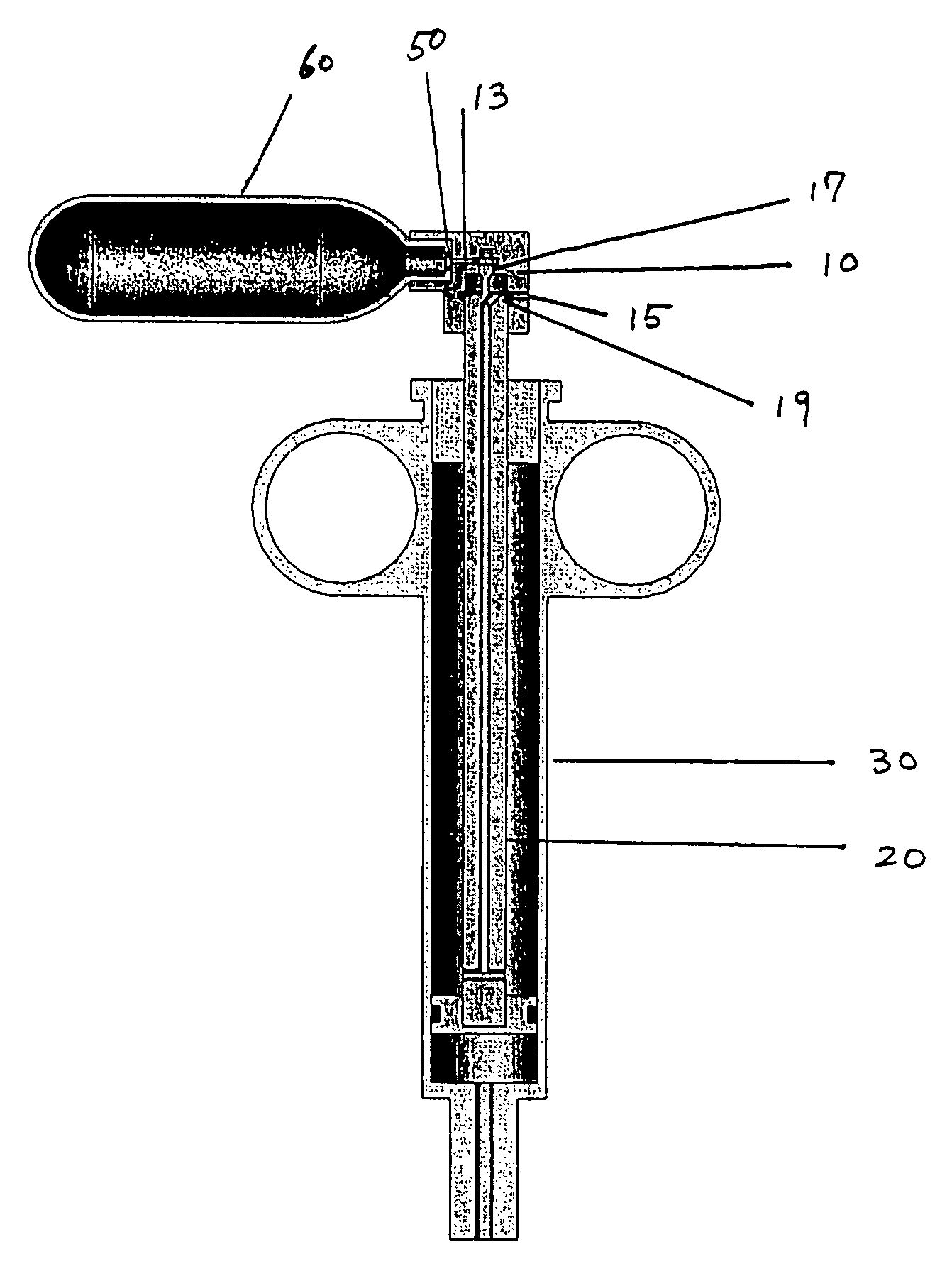
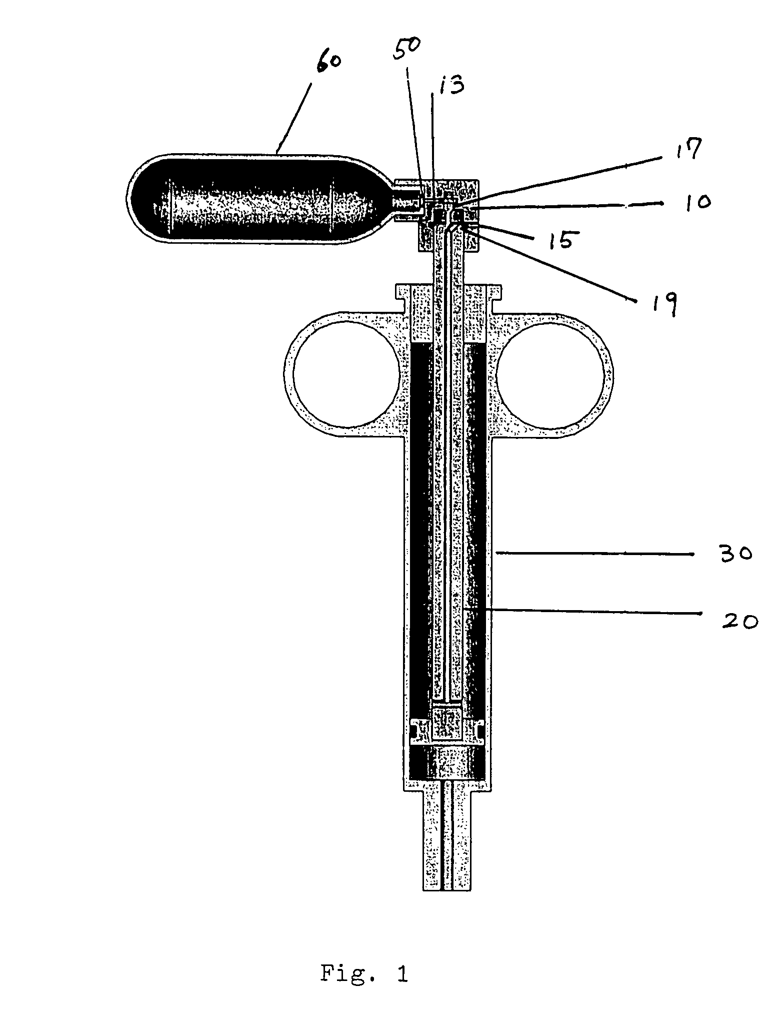
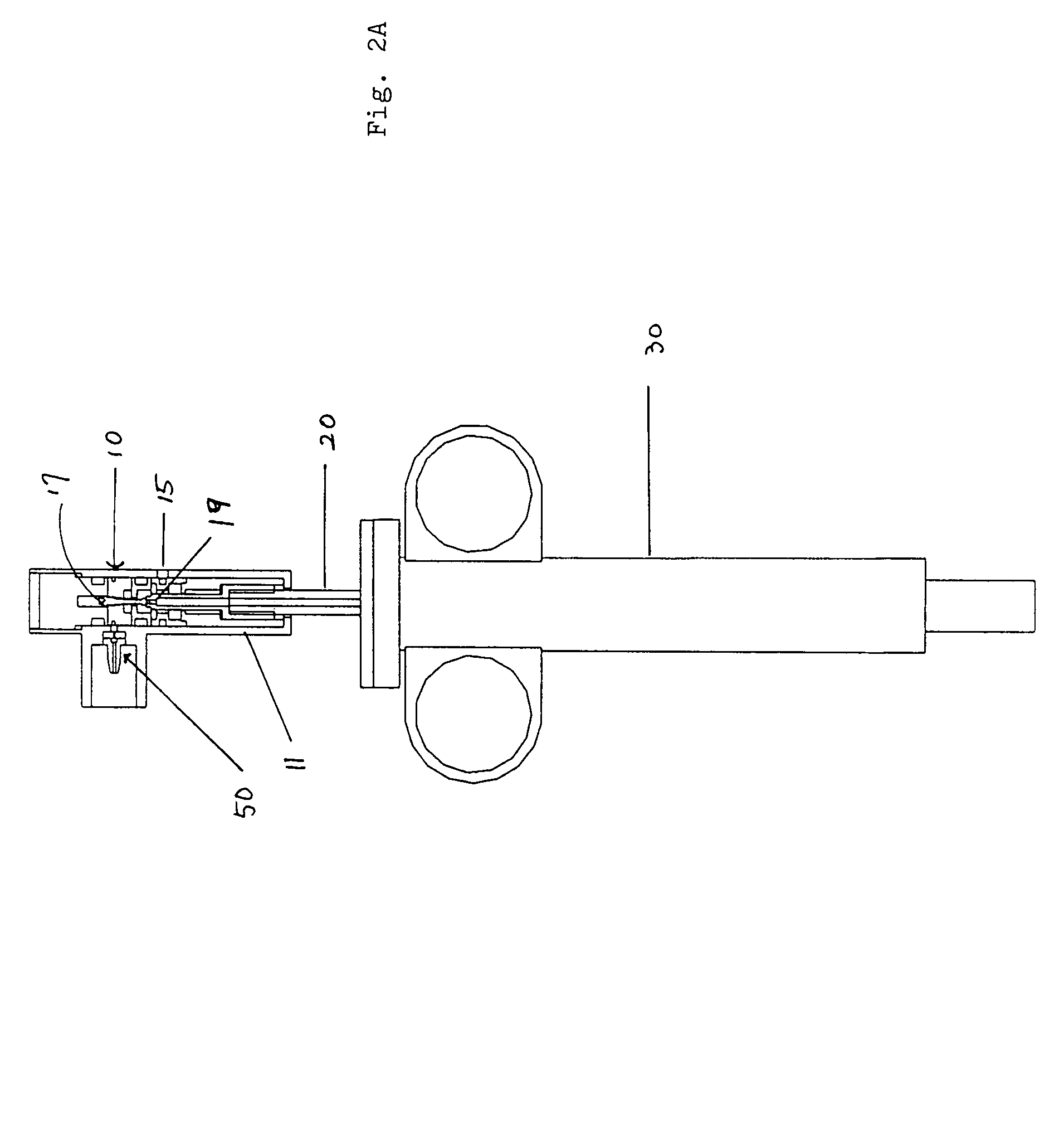
[0107]A first embodiment of the power-assisted syringe device is shown in alternative cross-sectional views by FIGS. 1, 2A and 2B respectively. FIG. 1 shows a cross-sectional perspective view of this embodiment of the power assisted syringe. FIGS. 2A and 2B are schematic illustrations of a power assisted syringe device of FIG. 1 that has been successfully tested. FIG. 2A shows a cross-sectional schematic view of an assembled device, while FIG. 2B shows a cross-sectional schematic view of an disassembled device.

[0108]As a further aid, FIGS. 3A to 3D show exploded views of these same assemblies. As seen therein, the portable and self-contained power assisted syringe comprises a manually controlled valve housing assembly 10, a plunger assembly 20, a syringe barrel assembly 30, attachment means 50 for connecting a portable source of pressurized gas to the value housing assembly 10, and a portable pressurized gas source 60 (seen as a miniaturized gas cylind...

second embodiment

2. A Preferred Second Embodiment

[0146]A second embodiment of the power-assisted syringe is illustrated by FIGS. 6-9 respectively. This second embodiment is structurally and functionally similar in every respect—but two—to the first embodiment described above. The substantive differences are: (i) a plunger tube member in the plunger assembly which, for most of its linear length, is only slightly smaller in dimensions and internal spatial volume than the size and volume of the lumen in the barrel assembly; and (ii) the pressurized gas from its source is directed into and is contained solely and exclusively within the hollow channel of the plunger tube member without ever entering into the lumen of the syringe barrel as such.

[0147]FIG. 6 presents a perspective view off this second embodiment for the assembled power-assisted syringe; and FIG. 7 schematically shows the component parts of the unassembled power-assisted syringe. As seen therein, the portable and self-contained power assist...

third embodiment

3. A Preferred Third Embodiment

[0153]A third embodiment of the power-assisted syringe is illustrated by FIGS. 10-13 respectively. This third embodiment is structurally and functionally similar in every substantive respect—but two—to the first embodiment described previously herein. The substantive differences are: (i) the valve assembly is attached to the syringe on the side of the barrel assembly; and (ii) the pressurized gas from its canister source is directed into and is contained solely and exclusively within the lumen of the syringe barrel as such—without ever entering into or travelling through the hollow channel of the plunger member in the plunger assembly.

[0154]FIG. 10 illustrates a perspective view of this third embodiment for an assembled power-assisted syringe; and FIGS. 11 and 12 respectively schematically shows the component parts of an assembled power-assisted syringe in front and side cross-sectional views. As seen therein, the power-assisted syringe device has a sl...


PUM


Abstract

A self-contained and hand-held power-assisted syringe is provided which is suitable for the controlled injection of fluid material during medical procedures such as coronary angiography procedures which utilize small-bore and small sized guide catheter systems. The present invention provides a greater degree of injection power on-demand than was previously possible in a portable and hand-held syringe; and it can deliver larger volumes of radiopaque contrast medium at greater pressures than was previously possible using a conventional manual syringe. The power assisted syringe, along with all components necessary for its effective use and operation, may be pre-packaged and steriled within a single container and then disposed of after use.

Description

PRIORITY CLAIM[0001]The present invention was first filed as U.S. Provisional Patent Application Ser. No. 60 / 473,739 on May 28, 2003.FIELD OF THE INVENTION[0002]The present invention is directed to the field of medical devices and more particularly to an integrated, hand-held power assist syringe device and its uses.BACKGROUND OF THE INVENTION[0003]Cardiovascular disease is the leading cause of death in the United States, and approximately one million people die of it annually. For this reason, contrast angiography is today an integral part in the diagnosis and treatment of cardiovascular disease. In the year 2000, U.S. cardiologists performed approximately two million diagnostic and therapeutic angiographic procedures according to data from Health Resources Utilization Branch of Center for Disease Control and Prevention / National Center for Health Statistics.[0004]Also, despite recent advances in non-invasive imaging techniques, angiography remains the gold standard for diagnosis of...

Claims


Application Information

Patent Timeline
Patent Type & Authority Patents(United States)
IPC IPC(8): A61M37/00A61M5/00A61M5/20
CPCA61M5/2053A61M5/007A61M2205/581A61M2205/583
Inventor KIM, DUCKSOOSMITH, JR., JOSEPH L.CRUNKLETON, JAMES A.
Owner KIM DUCKSOO
Why Eureka
Try Eureka