Primer, primer set, and nucleic acid amplification method and mutation detection method using the same

a primer set and primer technology, applied in the field of primer set, primer set, and nucleic acid amplification method and mutation detection method using the same, can solve the problems of cost, for example, and the emission of fluorescence of conventional fluorescent substances

Active Publication Date: 2011-11-29
DNAFORM
View PDF21 Cites 9 Cited by
  • Summary
  • Abstract
  • Description
  • Claims
  • Application Information

AI Technical Summary

Benefits of technology

[0517]As shown in FIG. 27, it was possible to read the fluorescence of the blotted spots at room temperature with a fluorescence imaging system without carrying out washing repeatedly after the blotting assay. As a result of the incubation with the probes, when the ODN (anti4.5S) had been added, strong fluorescence emission derived from the spots of 4.5S sequence was obtained, but the fluorescence emission derived from the spots of B1 sequence was ignorable. By contrast, when the ODN (antiB1) had been added, the B1 spots exhibited strong fluorescence but only very weak fluorescence was observed from the 4.5S spots. Thus, the DNA oligomers prepared in this reference example can realize an assay that is clearly different from a conventional blotting assay in requiring neither a cumbersome multistep washing process nor an antibody or enzyme treatment process after blotting. Furthermore, unlike the on-off oligomer such as a molecular beacon, the DNA oligomers of the present invention allows a plurality of fluorochrome-labeled portions to be introduced easily thereinto and thereby allows fluorescence intensity further to be increased. This is a great advantage of the present invention. The fluorochrome-labeled portions each may be, for example, one contained in [113](4) nucleotide as in this reference example. As described above, with respect to DNA oligomers with two [113](4) nucleotides incorporated therein, the change in fluorescence properties caused by hybridization with a target DNA fragment was confirmed in this reference example. Thus, it also is clear that DNA oligomers with two [113](4) nucleotides incorporated therein can be used as primers.
[0518]Poly T DNA oligomer (the ODN2 described above) containing a dye with a linker length n of 4 used in Example 8 was introduced into a cell by microinjection technique using a micro glass tube, and the fluorescence emission was then measured with an inverted microscope equipped with a mercury lamp, a cooled CCD camera, and a fluorescence filter set (for YFP). FIGS. 28 to 30 show the results. FIG. 28 is a photograph taken in differential interferometry, FIG. 29 is a photograph taken during fluorescence observation, and FIG. 30 shows FIGS. 28 and 29 that were superimposed on each other. As shown in the figures, the fluorescence DNA oligomer (labeling substance) of the present invention was bonded to a poly(A) end sequence of mRNA that was expressed intracellularly, and thereby emitted light. That is, the labeled DNA oligomer of the present invention is effective for not only in vitro gene detection but also in vivo gene detection.Reference Example 3
[0519]Further, a common fluorescent dye, Cy5, was bonded to the ODN2 (with a sequence of 5′-d(TTTTTT[113](4)TTTTTT)-3′) by a conventional method, which further was introduced into a cell by the aforementioned method. In this case, Cy5 was added to the 5′ end of the ODN2 with an automated DNA synthesizer to be bonded thereto in the process of synthesizing the ODN2 (with a sequence of 5′-Cy5-d(TTTTTT[113](4)TTTTTT)-3′). The fluorescence emission was measured with a laser scanning confocal microscope. FIG. 31 shows the result. FIG. 31A shows fluorescence derived from Cy5, with the fluorescence with a wavelength of at least 650 nm being obtained by excitation at 633 nm. FIG. 31B shows fluorescence derived from two thiazole orange portions, with the fluorescence between 505 nm and 550 nm being obtained by excitation at 488 nm. As shown in the figures, the ODN2 was bonded to the poly(A) end sequence of mRNA that was expressed intracellularly, and thereby emitted light. This allowed the distribution of intracellular mRNAs to be traced. As described above, a plurality of types of dyes (atomic groups that exhibit fluorescence) may be introduced into the compound or nucleic acid of the present invention. This also allows multicolor detection to be carried out, since, for example, respective dyes are different in λmax of fluorescence from each other.Reference Example 4
[0520]The aforementioned ODN2 (with a sequence of 5′-d(TTTTTT[113](4)TTTTTT)-3′) was injected into a cell nucleus by the aforementioned method, and the fluorescence emission was traced with the laser scanning confocal microscope from immediately after injection (0 second) to approximately 4.5 minutes (excitation at 488 nm, and fluorescence obtained between 505 nm and 550 nm). FIG. 32 shows the result. FIG. 32 include 11 diagrams that show the progress after injection of the ODN2, from left to right and from upper row toward lower row. In each diagram, the elapsed time (after injection of the ODN2) is as indicated in Table 8 below. As shown in FIG. 32, it was confirmed that the ODN2 was concentrated in the cell nucleus immediately after injection thereof but was dispersed gradually throughout the cell together with mRNA (poly A) hybridized therewith. According to the present invention, it also is possible to trace mRNA in the manner as described above.
[0521]TABLE 8 0 sec 8 sec 38 sec 68 sec 98 sec128 sec158 sec188 sec218 sec248 sec278 sec—Reference Example 5
[0522]An ODN was synthesized, in which the number of Ts located on each side of [113](4) of the ODN2 was increased to 24. This is referred to as “ODN7”. This was synthesized by the same method as that of synthesizing the ODN2. The sequence of the ODN7 is: 5′-d(TTTTTTTTTTTTTTTTTTTTTTTT[113](4)TTTTTTTTTTTTTTTTTTTTTTTT)-3′) (SEQ ID NO. 13). This was injected into a cell nucleus by the same method as that employed in Example 22, and the fluorescence intensity was measured. FIG. 33 shows a fluorescence photograph taken after a lapse of a certain period of time. The ODN7 was concentrated in the cell nucleus immediately after injection but was dispersed gradually throughout the cell together with mRNA (poly A) hybridized therewith, as in Example 22, and finally, it was dispersed around the cell nucleus as shown in FIG. 33.Reference Example 6Multicolor Detection

Problems solved by technology

However, there is a possibility that a conventional fluorescent substance may emit fluorescence, even when, for example, no double helix structure has been formed.
However, it has problems in, for example, cost due to the introduction of two types of fluorescent dyes.

Method used


Image

  • Primer, primer set, and nucleic acid amplification method and mutation detection method using the same
  • Primer, primer set, and nucleic acid amplification method and mutation detection method using the same
  • Primer, primer set, and nucleic acid amplification method and mutation detection method using the same

Examples


examples

[0366]The present invention is described in further detail using the following examples. However, the present invention is not limited by the following examples. In the description below, “ODN” denotes oligodeoxyribonucleotide (DNA oligomer).

[Measurement Conditions and Others]

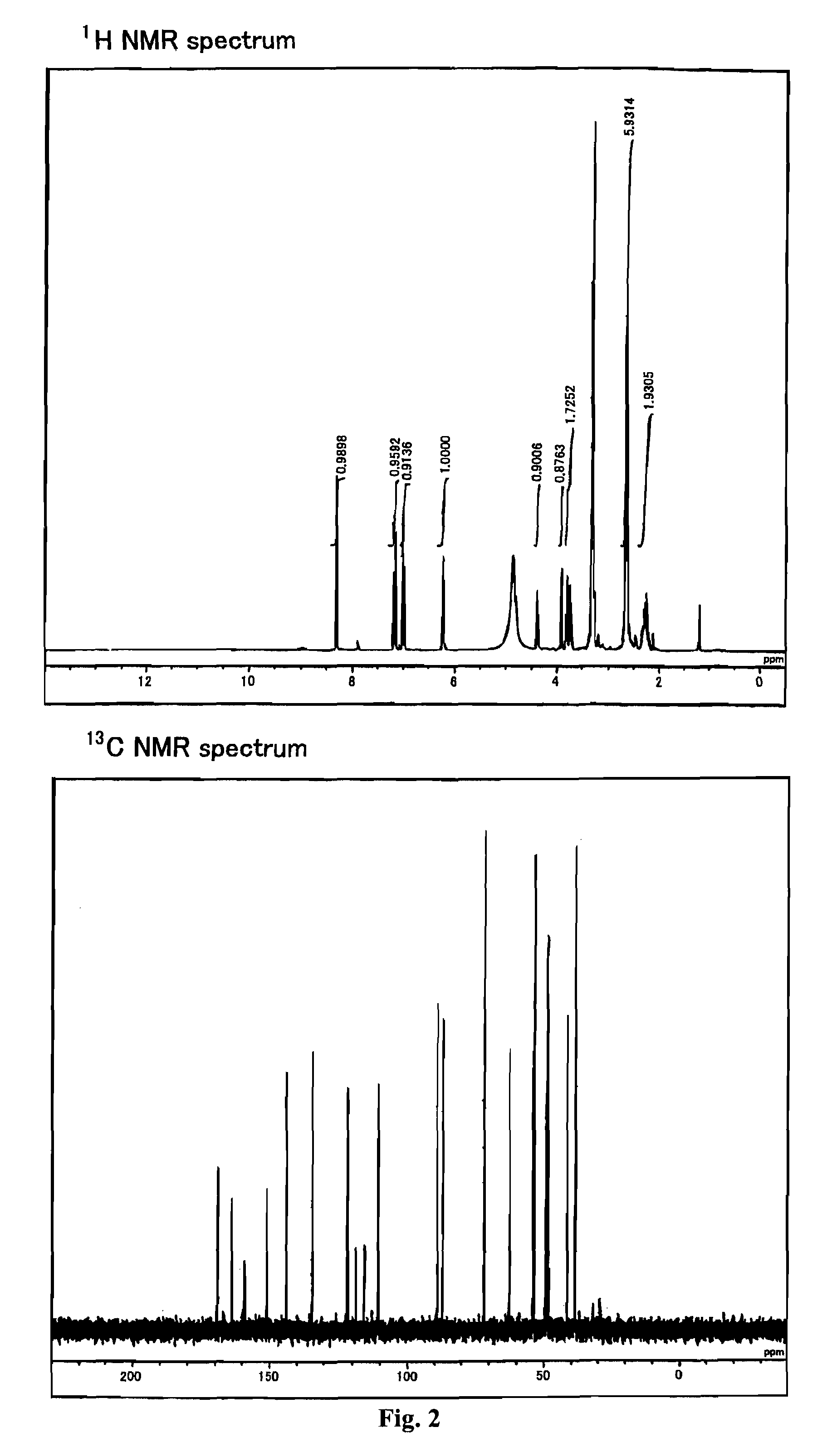
[0367]The reagents and solvents used herein are commercially available. N-hydroxysuccinimidyl ester of biotin used herein was one available from PIERCE. The silica gel for purifying a compound used herein was Wako gel C-200 (Wako Pure Chemical Industries, Ltd.). 1H, 13C, and 31P NMR spectra were measured with JNM-α400 (trade name) available from JEOL (JOEL Ltd.). The coupling constant (J value) is indicated in hertz (Hz). The chemical shift is indicated in ppm. Dimethylsulfoxide (δ=2.48 in 1HNMR, δ=39.5 in 13CNMR) and methanol (δ=3.30 in 1HNMR, δ=49.0 in 13CNMR) were used for internal standards. For 31PNMR measurement, H3PO4 (δ=0.00) was used as an external standard. The ESI mass spectrum was measured using Bru...

examples 1 to 3

[0369]According to the following Scheme 1, compounds 102 and 103 including two active amino groups protected with trifluoroacetyl groups, respectively, were synthesized (produced), and further phosphoramidite 104 was synthesized.

[0370]

Scheme 1—Reaction Reagent and Reaction Conditions:

(a) (i) N-hydroxysuccinimide, EDC / DMF, (ii) tris(2-aminoethyl)-amine / CH3CN, (iii) CF3COOEt, Et3N; (b) DMTrCl / pyridine; (c) 2-cyanoethyl-N,N,N′,N′-tetraisopropyl phosphoramidite, 1H-tetrazole / CH3CN.

[0371]Scheme 1 is described below in further detail.

example 1

Synthesis of 2-[2-[N,N-bis(2-trifluoroacetamidoethyl)]-aminoethyl]carbamoyl-(E)-vinyl)-2′-deoxyuridine (Compound 102)

[0372]The starting material, (E)-5-(2-carboxyvinyl)-2′-deoxyuridine (Compound 101), was synthesized according to Tetrahedron 1987, 43, 20, 4601-4607. That is, first, 71 mL of 1,4-dioxane was added to 430 mg of palladium acetate (II) (FW 224.51) and 1.05 g of triphenylphosphine (FW 262.29), and further 7.1 mL of triethylamine (FW 101.19, d=0.726) was added thereto. This was heated and stirred at 70° C. After the reaction solution was changed from reddish brown to blackish brown, 14.2 g of 2′-deoxy-5-iodouridine (FW 354.10) and 7.0 mL of methyl acrylate (FW 86.09, d=0.956) that were suspended in 1,4-dioxane were added thereto. This was heat-refluxed at 125° C. for one hour. Thereafter, it was filtered while it was still hot, the residue was washed with methanol, and then the filtrate was recovered. After the solvent was evaporated from the filtrate under reduced pressur...


PUM

PropertyMeasurementUnit
carbon numberaaaaaaaaaa
wavelengthaaaaaaaaaa
temperatureaaaaaaaaaa

Abstract

The present invention provides a primer that effectively can detect, for example, the double helix structure of a nucleic acid. The primer is a labeled nucleic acid containing at least one structure represented by the following formula (16),where B is an atomic group having a nucleobase skeleton, E is an atomic group having a deoxyribose skeleton, a ribose skeleton, or a structure derived from either one of them, or an atomic group having a peptide structure or a peptoid structure, and Z11 and Z12 are each an atomic group that exhibits fluorescence and are identical to or different from each other.

Description

BACKGROUND OF THE INVENTION[0001]1. Field of the Invention[0002]The present invention relates generally to a primer set for amplifying a target nucleic acid sequence, and a nucleic acid amplification method and mutation detection method that use the same.[0003]2. Description of the Related Art[0004]In, for example, genetic diagnoses of diseases and gene expression analysis, it is necessary to detect a target nucleic acid having a specific sequence. For the detection, fluorescence is used widely. Specifically, a known method uses a fluorescent substance whose fluorescence intensity increases with an increase in target nucleic acid sequence. A typical example of the fluorescent substance is a substance that intercalates into a double helix structure and emits fluorescence by irradiation with excitation light. When a target nucleic acid sequence is amplified using a primer labeled with such a fluorescent substance, for instance, the primer hybridizes to a target nucleic acid sequence o...

Claims


Application Information

Patent Timeline
Patent Type & Authority Patents(United States)
IPC IPC(8): C12Q1/68C12P19/38C07H21/02
CPCC12Q1/6853C12Q2525/117C12Q2563/107C12Q2565/101C09B23/04C12Q1/6827C12Q1/686C12Q1/6874
Inventor HAYASHIZAKI, YOSHIHIDEOKAMOTO, AKIMITSULEZHAVA, ALEXANDERKOGO, YASUSHI
Owner DNAFORM
Why Eureka
Try Eureka