Electrolytic capacitor

a capacitor and electrolytic technology, applied in the direction of fixed capacitors, casings/cabinets/drawers, electrical equipment casings/cabinets/drawers details, etc., can solve the problems of low reliability of quaternary ammonium salt-based electrolytic solution, and no aluminum electrolytic capacitor has been realized to satisfy such properties, so as to reduce specific resistance, improve long-term reliability of electrolytic capacitor electrical properties, and suppress the effect of withstand voltag

Active Publication Date: 2012-02-14
NICHICON CORP
View PDF17 Cites 7 Cited by
  • Summary
  • Abstract
  • Description
  • Claims
  • Application Information

AI Technical Summary

Benefits of technology

[0032]The electrolytic capacitor of the present invention employs an electrolytic solution containing a tricyanomethide salt as an electrolyte and having a water content of 3.0 wt % or less. Thus, a specific resistance can be reduced while reduction in withstand voltage is suppressed. Further, long-term reliability of electrical properties of the electrolytic capacitor can be improved.
[0033]In the case of applying a voltage under a condition where water easily enters from outside into the capacitor such as in a moisture tolerance test, alkalization of the electrolytic solution occurs in a vicinity of an cathode lead and ooze occurs due to degradation of sealing rubber. However, in the present invention, ooze can be prevented by sealing at least a cathode lead insertion port of the sealing rubber with a resin.

Problems solved by technology

However, the quaternary ammonium salt-based electrolytic solution has low reliability because its base component may ooze from a cathode sealed part.
However, no aluminum electrolytic capacitor has been realized to satisfy such properties.
Thus, such an imidazolium salt or a pyridinium salt has problems such as corrosion of an electrode, and is not a compound to be used for the aluminum electrolytic capacitor.

Method used


Image

  • Electrolytic capacitor
  • Electrolytic capacitor
  • Electrolytic capacitor

Examples


examples

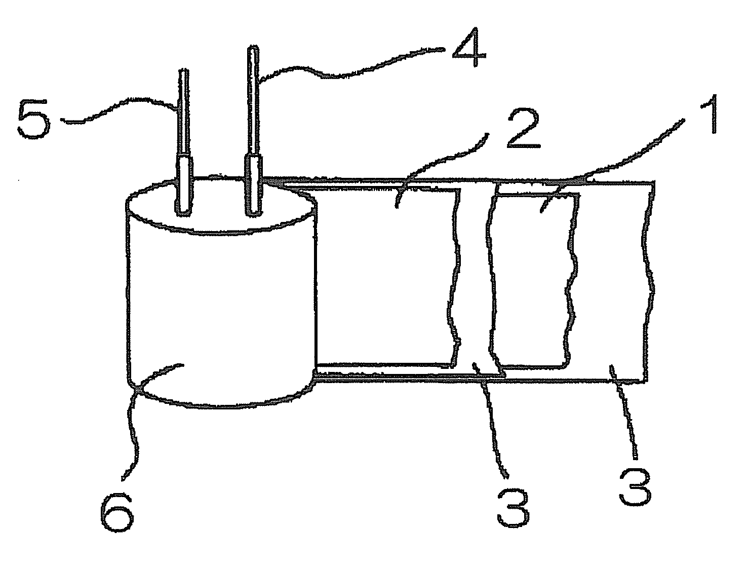
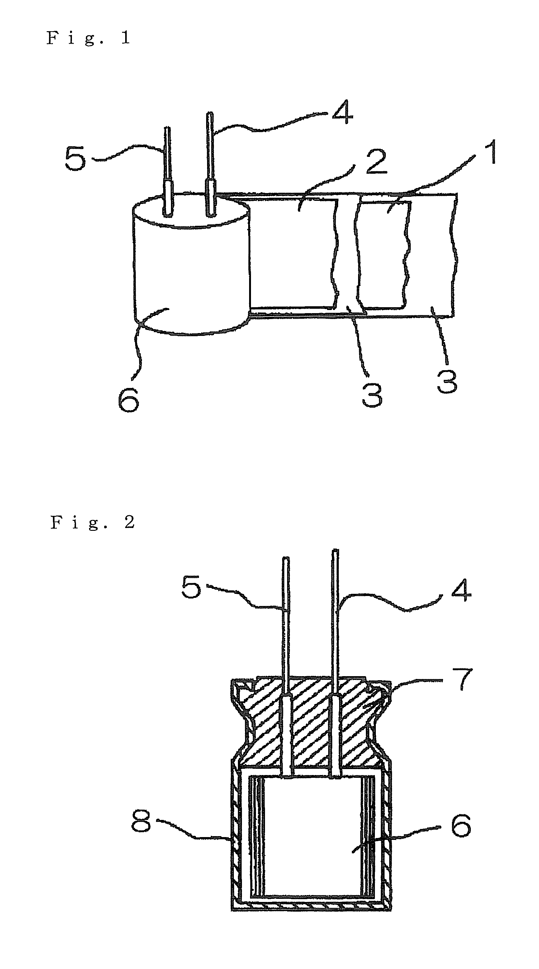
[0107]The aluminum electrolytic capacitor of the present invention was produced through the procedure as described below.

[0108]The present invention may be applied to any structure. However, in Examples, the present invention will be described by using the structures shown in FIGS. 1 and 2 for clarity. Hereinafter, aluminum electrolytic capacitors to be used in Examples have the same structures.

[0109]First, electrolytic solutions having respective compositions described in Tables 1 to 3 were prepared. At this time, predetermined dehydration treatment was performed so as to adjust a water content of the electrolytic solution before adding pure water to substantially 0. Then, pure water was added in an amount described in Tables 1 to 3. Next, a capacitor element was formed (rated voltage of 6.3 V-1,000 μF (Φ10×12.5 mmL)) by rolling an anode foil and a cathode foil each subjected to etching treatment and oxide film formation treatment through a Manila hemp-based separator. The capacito...


PUM


Abstract

Provide is an aluminum electrolytic capacitor exhibiting low specific resistance and low impedance property and realizing high reliability. An electrolytic capacitor has a structure in which: a capacitor element which is formed by rolling an anode foil and a cathode foil each connected with an electrode extraction lead through a separator and which is impregnated with a drive electrolytic solution is included in a cylindrical outer case having a closed-end; and an open end of the outer case is sealed with an elastic sealing body, in which: the drive electrolytic solution contains a tricyanomethide salt represented by the below-indicated chemical formula (1); and the drive electrolytic solution has a water content of 3.0 wt % or less:where, R represents a cation pairing with a tricyanomethide ion in formation of a tricyanomethide salt.

Description

TECHNICAL FIELD[0001]The present invention relates to a long-life electrolytic capacitor to be used for electronic devices and having low impedance in a high frequency region.BACKGROUND ART[0002]An electrolytic capacitor refers to a capacitor employing as an electrode a so-called valve metal such as aluminum, tantalum, or niobium and including as a dielectric an oxide film layer formed through anode oxidation.[0003]An aluminum electrolytic capacitor generally has a structure shown in FIGS. 1 and 2. A capacitor element 6 is formed by rolling an anode foil 1 and a cathode foil 2 each subjected to etching treatment and oxide film formation treatment through a separator 3. Then, the capacitor element is impregnated with an electrolytic solution, and included in a cylindrical outer case 8 having a closed-end.[0004]Next, anode and cathode extraction leads 4 and 5 are inserted through and extracted from through-holes formed on an elastic sealing body 7. The sealing body (elastic sealing bo...

Claims


Application Information

Patent Timeline
Patent Type & Authority Patents(United States)
IPC IPC(8): H01G9/025
CPCH01G9/035H01G9/10H01G11/62H01G9/145Y02E60/13H01G9/00
Inventor TANI, SATOSHIONOUE, SEITAROUEDA, TAKAYUKIMIZUTA, KEIICHIROHASHIMOTO, HIRONOBUKASAHARA, TAISUKE
Owner NICHICON CORP
Why Eureka
Try Eureka