
Process for converting syngas to liquid products with microorganisms on two-layer membrane

a two-layer membrane and microorganism technology, applied in the field of biochemical conversion of co and mixture, can solve the problems of inability of conventional yeasts to ferment csub>5/sub>sugar to ethanol and the total unfermentability of such organisms of lignin components

Inactive Publication Date: 2012-06-12
SYNATA BIO INC
View PDF47 Cites 6 Cited by
  • Summary
  • Abstract
  • Description
  • Claims
  • Application Information

AI Technical Summary

Benefits of technology

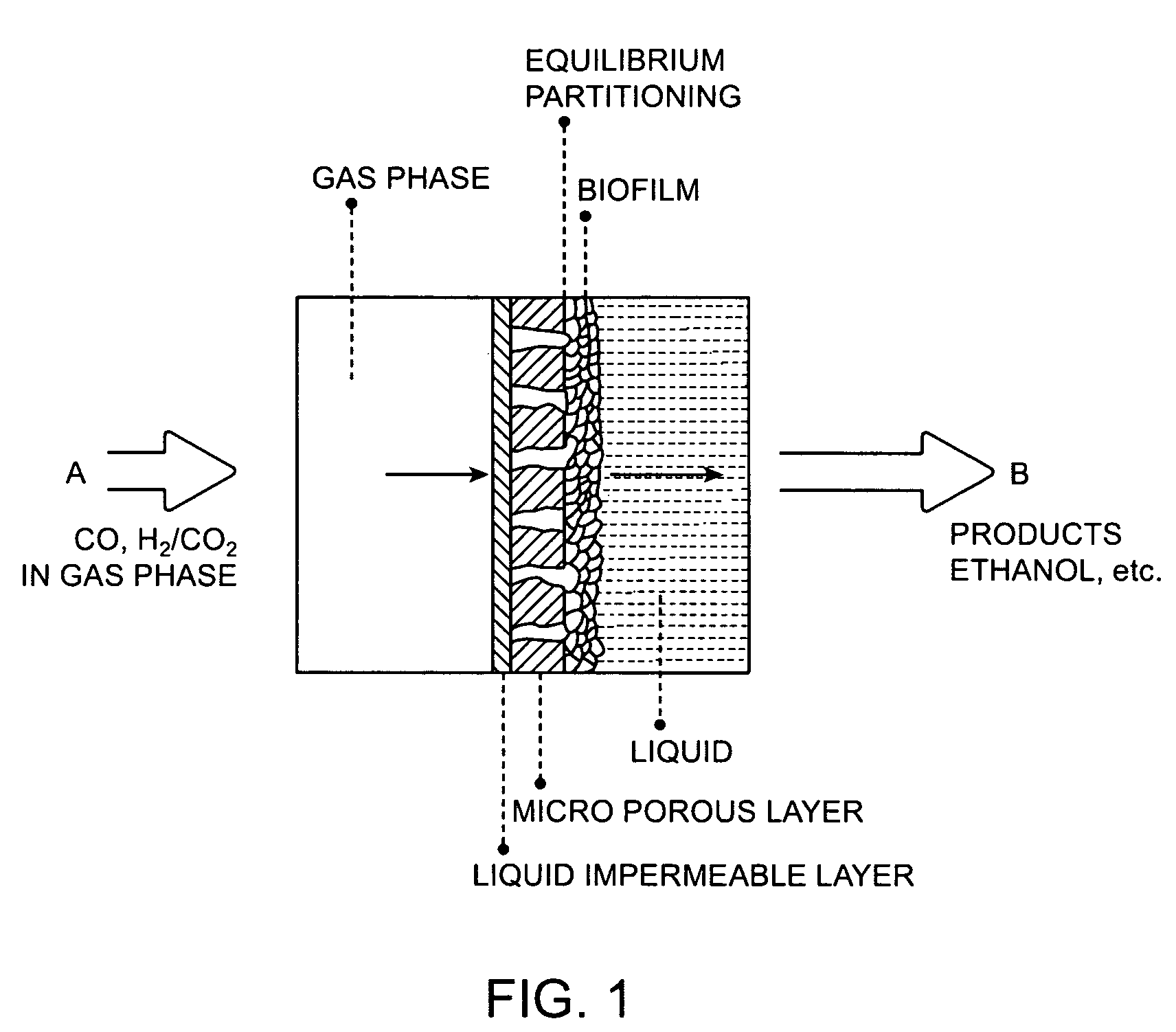
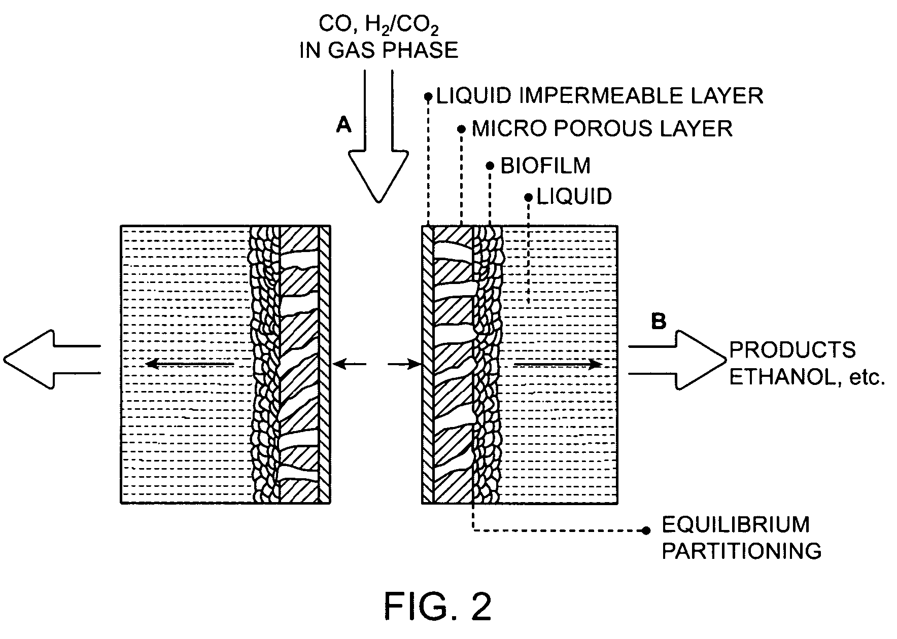
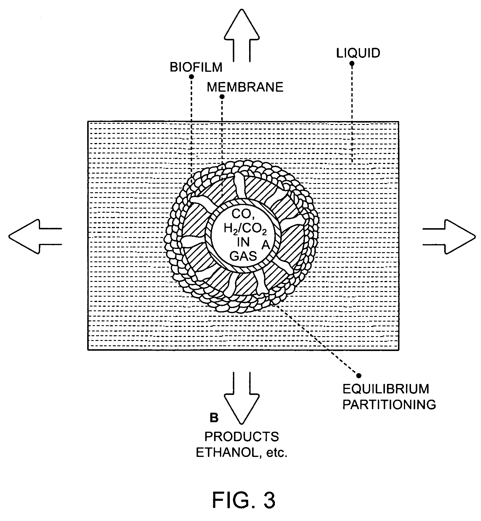
The patent describes a membrane system that can convert gas to liquid products using microorganisms. The system includes a membrane with a microporous layer and a liquid impermeable layer that creates a stable system for producing liquid fuels and chemicals. The membrane supports a biofilm on its surface, which contains microorganisms that convert the gas to the desired products. The system has a high efficiency and can produce ethanol and other chemicals at a high concentration. The membrane system can also remove carbon dioxide from the gas and return it to the bioreactor for further conversion. Overall, the system provides a highly efficient and economical way to produce liquid products from gas.

Problems solved by technology

The availability of agricultural feedstocks that provide readily fermentable carbohydrates is limited because of competition with food and feed production, arable land usage, water availability, and other factors.
However, the very heterogeneous nature of lignocellulosic materials that enables them to provide the mechanical support structure of the plants and trees makes them inherently recalcitrant to bioconversion.
Furthermore, conventional yeasts are unable to ferment the C5 sugars to ethanol and lignin components are completely unfermentable by such organisms.
For all of these reasons, processes based on a pretreatment / hydrolysis / fermentation path for conversion of lignocellulose biomass to ethanol, for example, are inherently difficult and often uneconomical multi-step and multi conversion processes.
And very large quantities of these gases are required.
Furthermore, the anaerobic microorganisms that bring about these bioconversions generate very little metabolic energy from these bioconversions.
The agitated vessels require a lot of mechanical power often in the range of 4 to 10 KW per 1000 gallons—uneconomical and unwieldy for large scale fermentations that will be required for such syngas bioconversions.
The fluidized or fluid circulating systems cannot provide the required gas dissolution rates.
These systems are expensive and require extensive maintenance and cleaning of the membranes to maintain the fluxes and other performance parameters.
They suffer from either being very large or unable to provide sufficient gas dissolution rates.
Existing composite and dense membranes have limited flux for CO and H2 transfer due to low permeability of the membrane of the non-porous layer or long diffusion path (especially for the dense membrane).

Method used


Image

  • Process for converting syngas to liquid products with microorganisms on two-layer membrane
  • Process for converting syngas to liquid products with microorganisms on two-layer membrane
  • Process for converting syngas to liquid products with microorganisms on two-layer membrane

Examples


example 1

[0063]The membrane permeance of syngas components was measured for Membrane A, a gas transfer membrane module Model MHF0504MBFT from Mitsubishi Rayon Engineering (Tokyo, Japan). The module contains composite hollow fiber membranes with a triple-layer construction, consisting of a thin liquid impermeable layer sandwiched between two porous layers. The fiber outer diameter is approximately 280 μm and inner diameter approximately 200 μm. The nominal membrane surface area in the module was 0.6 m2. A source of syngas, containing 39.0% CO, 33.5% H2, 23.1% CO2 and 4.4% N2, was connected to the lumen inlet of the module, while the lumen outlet was closed with a shut-off valve. The syngas feed pressure was maintained at a desired level, and the feed flow rate was measured with a calibrated flow meter. Syngas components passed through the membrane into the shell side of the module, and the permeate flow rate was measured with a bubble flow meter. Pressures at the lumen inlet, lumen outlet and...

example 2

[0064]A membrane module measuring 4″ diameter and 40″ length and containing a gas transfer membrane described in Example 1 was used as a membrane supported bioreactor for the conversion of carbon monoxide and hydrogen into ethanol. The active membrane surface area of the module was 17.1 m2, based on fiber outer diameter. The packing density of the module, calculated as the volume occupied by the fibers divided by the internal volume of the module, was 16%. The membrane module was housed in constant temperature chamber at 37° C. and connected to a 10-liter BIOSTAT Bplus Fermentor from Sartorius AG (Goettingen, Germany). The fermentor initially contained 8 liters of the fermentation medium, which was agitated at 300 rpm and maintained at 37° C. The fermentor was maintained under anaerobic conditions. The fresh fermentation medium contained the components listed in Tables 2 & 3(a)-(d). Initially, at t=0 hr the fermentor was operated in the batch mode without connecting to the membrane ...


PUM

PropertyMeasurementUnit
thicknessaaaaaaaaaa
surface areaaaaaaaaaaa
inner diameteraaaaaaaaaa

Abstract

Ethanol and other liquid products are produced by contacting syngas components such as CO or a mixture of CO2 and H2 with a surface of a membrane under anaerobic conditions and transferring these components in contact with a biofilm on the opposite side of the membrane. These steps provide a stable system for producing liquid products such as ethanol, butanol and other chemicals. The gas fed on the membrane's gas contact side transports through the membrane to form a biofilm of anaerobic microoganisms that converted the syngas to desired liquid products. A liquid impermeable layer of the membrane assists in establishing direct gas phase contact syngas components with the microorganisms. The system can sustain production with a variety of microorganisms and membrane configurations.

Description

CROSS REFERENCE TO RELATED APPLICATIONS[0001]This application is a continuation in part of U.S. application Ser. No. 11 / 781,717 filed Jul. 23, 2007, now abandoned which is an application claiming benefit under 35 USC 119(c) of U.S. Provisional Patent Application Ser. No. 60 / 942,938 filed Jun. 8, 2007.FIELD OF THE INVENTION[0002]This invention relates to the biological conversion of CO and mixtures of CO2 and H2 to liquid products.DETAILED DESCRIPTIONBackground[0003]Biofuels production for use as liquid motor fuels or for blending with conventional gasoline or diesel motor fuels is increasing worldwide. Such biofuels include, for example, ethanol and n-butanol. One of the major drivers for biofuels is their derivation from renewable resources by fermentation and bioprocess technology. Conventionally, biofuels are made from readily fermentable carbohydrates such as sugars and starches. For example, the two primary agricultural crops that are used for conventional bioethanol production...

Claims


Application Information

Patent Timeline
Patent Type & Authority Patents(United States)
IPC IPC(8): C12P7/54C12M1/00C12M1/12C12P7/30C12P7/06C12P7/16C12P7/04C12P7/40C12P7/52
CPCC12M21/12C12M23/44C12M25/10C12M29/16C12P7/04Y02E50/17Y02E50/10
Inventor DATTA, RATHINTSAI, SHIH-PERNGBASU, RAHULYOON, SEONG-HOON
Owner SYNATA BIO INC
Learn More