Lining of wellbore tubing

a technology of tubing and wellbore, which is applied in the direction of sealing/packing, drilling pipes, and wellbore/well accessories, etc., can solve the problems of challenging environment of wellbore tubing, and achieve the effect of strengthening the surface of the lining

Inactive Publication Date: 2013-03-12
SCHLUMBERGER TECH CORP
View PDF48 Cites 12 Cited by
  • Summary
  • Abstract
  • Description
  • Claims
  • Application Information

AI Technical Summary

Benefits of technology

[0012]We have found that the rate of reaction can be increased by increasing the intensity and hence the amount of actinic radiation, without detriment to the end result. We have found that it is possible to choose the reactants in the composition and the intensity and duration of the actinic radiation such that, within 30 seconds or less from the time when the composition is exposed to actinic radiation, polymerization can proceed to a point where the composition is no longer mobile.
[0046]A sleeve containing the liquid polymer may enclose it between inner and outer walls of the sleeve, with the outer wall being permeable by some of the liquid composition when the sleeve is pressed against the tubing. The sleeve may comprise a number of layers of reinforcing fabric, impregnated with the polymerisable liquid composition. A further possibility is that the sleeve has expandable metal parts on its inside wall, which become adhered to the inside surface of the polymer lining of the tubing and so providing a stronger surface for the lining.

Problems solved by technology

Thus the interior of wellbore tubing presents a challenging environment both for the application of a polymerisable fluid composition and also for exposure of the composition to actinic radiation once the composition has been put in place.

Method used


Image

  • Lining of wellbore tubing
  • Lining of wellbore tubing
  • Lining of wellbore tubing

Examples


example 1

[0086]Some laboratory experiments were carried out to demonstrate features of embodiments of the present invention. Samples of polymerisable liquid composition were placed in an I-shaped plastic mould and polymerization was initiated by exposure to the radiation from a 6 W UV lamp (manufactured by UV products, and purchased from Fisher Scientic UK). The lamp was dual wavelength, emitting at wavelengths of 254 nm or 365 nm.

[0087]Curing kinetics were followed using a Nicolet FTIR (Fourier Transform Infra-Red) spectrometer with a ZnSe ATR (attenuated total reflection) plate. The UV lamp was placed in the access port on the spectrometer, and the plate was irradiated during spectral acquisition. Changes in the height of the 1634 cm peaks was followed, this being the C═C stretch of the acrylate group. As the, polymerization reaction proceeded the C═C bonds were eliminated and the peak height dropped. It was observed that the polymerization reaction took place over a period of ten minutes ...

example 2

[0102]A laboratory experiment was carried out to examine the effect of radiation intensity on speed of reaction. Bis phenol A ethoxylate diacrylate containing 0.2% (bis (eta 5-2,4-cyclopentadien-1-yl)bis [2,6-difluoro-3-(1H-pyrrol-1-yl)phenyl]titanium as photoinitiator was irradiated with white light having a peak wavelength of 555 nm. The rate of reaction was followed using the Fourier Transform Infra-Red spectrometer mentioned in Example 1 to monitor the decrease of the vinyl (1,400 cm−1) peak area, relative to the carbonyl (1,700 cm−1) peak area. Irradiation was at either 1,200 klux or 120 klux (equivalent to 190 or 19 mW / cm−2, respectively). A plot of the extent of reaction against time is shown as FIG. 13. Not all acrylate groups react because the polymer chains cease to grow when the reaction mixture becomes solid, but it can be seen that the higher intensity of illumination leads more rapidly to a similar level of completion, with the reaction being largely complete in less t...

example 3

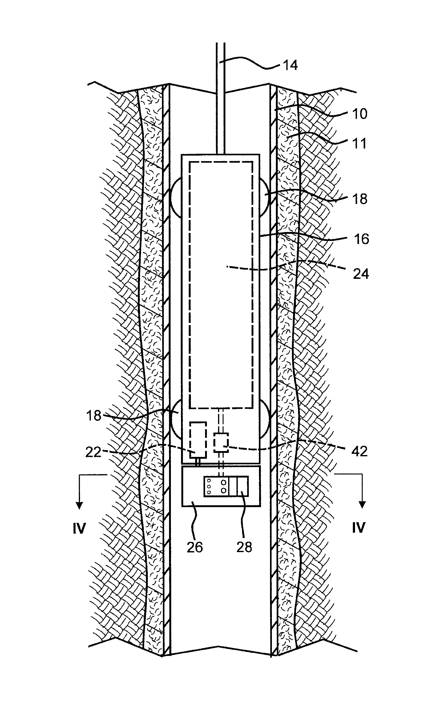
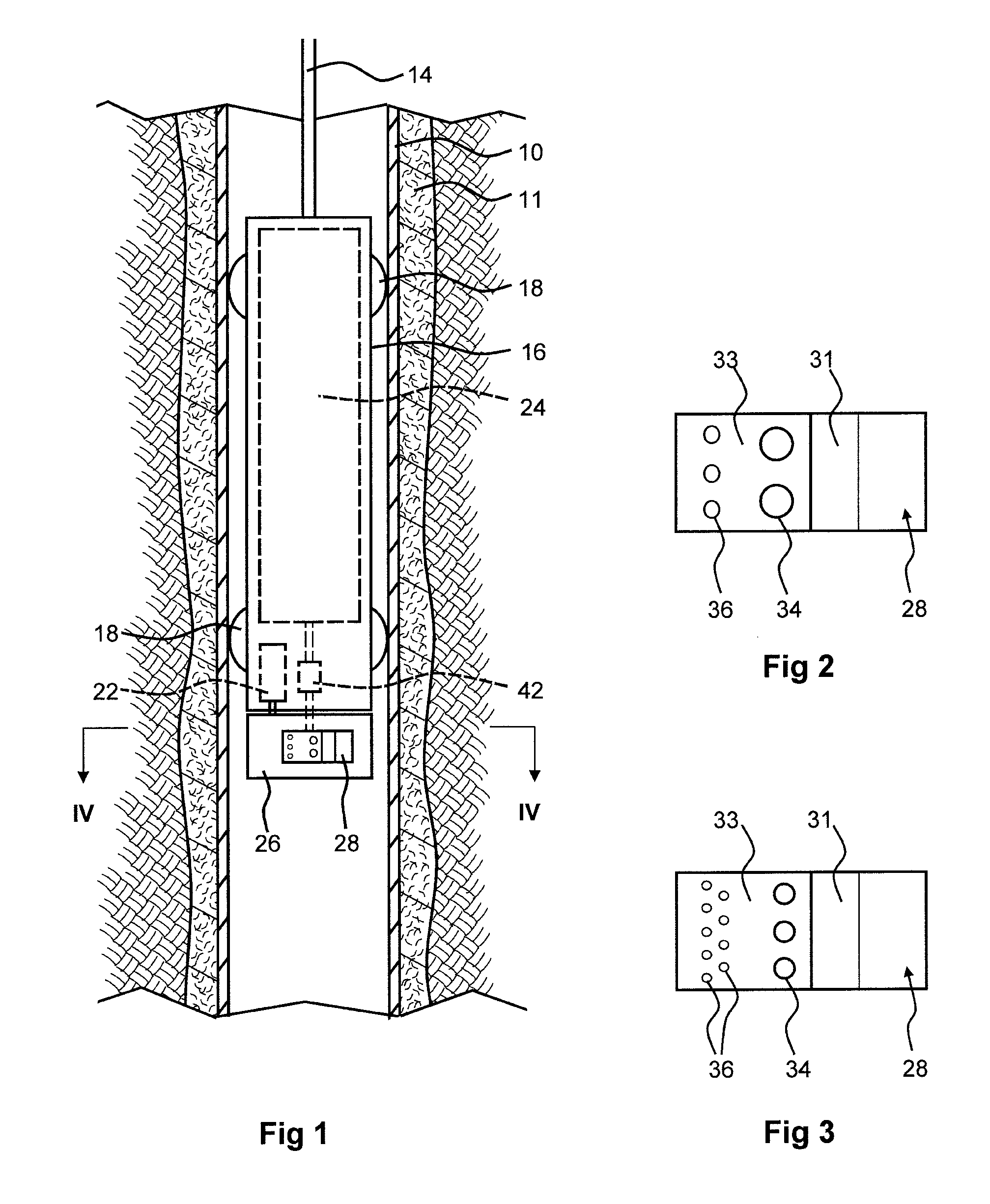
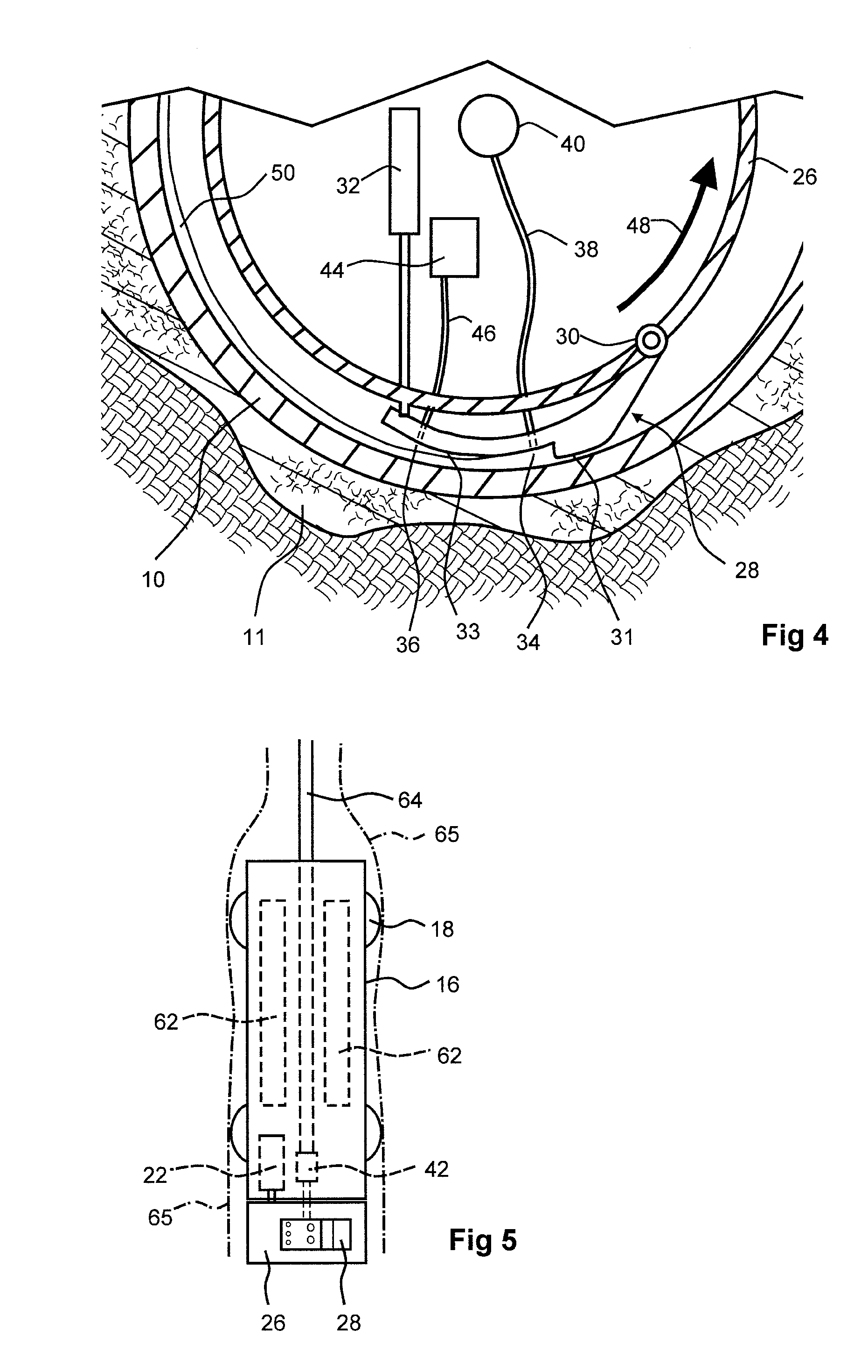
[0103]Laboratory apparatus for applying polymerisable composition to the interior of a cylinder was constructed to have a dispensing outlet for liquid composition, followed by an outlet for ultraviolet radiation, similarly to the arrangement shown in FIGS. 1 to 4. This apparatus was used to apply a polymerisable liquid composition as shown in the following table to the interior of a clear acrylic cylinder and direct ultraviolet radiation onto the composition as it was applied. During application of the composition there was rotation and axial movement of the apparatus relative to the cylinder (For convenience in construction the cylinder was move and the apparatus was fixed). The cylinder was then inspected and found to have a band of rigid polymer extending as a helix adhered to its interior surface.

[0104]The polymerisable liquid composition contained

[0105]

ChemicalWeight %Bisphenol A (1.5) ethoxy diacrylate73.2Polyethyleneglycol diacrylate Mol. wt24.4260pentaerythritol tetraacrylat...


PUM

PropertyMeasurementUnit
wavelengthaaaaaaaaaa
temperaturesaaaaaaaaaa
wavelength rangeaaaaaaaaaa

Abstract

A method of lining tubing within a wellbore comprises applying a polymerisable fluid composition containing a photoinitiator to the interior surface of that tubing and initiating polymerisation of the composition by exposing it to actinic radiation, suitably light or ultraviolet with wavelength 250 to 800 nm. The composition is preferably stable against heat but polymerises quickly when exposed to the actinic radiation. The composition may be spread onto the tubing and exposed to actinic radiation as soon as it has been spread into a layer, suitably with a tool which skims the tubing surface with applicator pads for dispensing and spreading the composition, immediately followed by exposing the spread composition to actinic radiation. A second option is that the composition is provided as a sleeve which is expanded against the tubing, exposure to actinic radiation preferably then being achieved using light guides or light emitting diodes within the sleeve.

Description

FIELD OF THE INVENTION[0001]This invention relates to lining of tubing placed within a well bore. The process of lining the tubing may be carried out for various purposes, including repair, to protect the tubing against corrosion or damage, and to close off perforations which are no longer required.BACKGROUND OF THE INVENTION[0002]It is common practice that a wellbore leading to a subterranean reservoir, especially a hydrocarbon reservoir, is lined with a casing which is cemented in place in the wellbore. Often a production tube is positioned inside the casing. From time to time it may become necessary to replace or repair these tubular components. This may be done because of corrosion of the tubing, with the risk of failure, or because of damage to the tubing or the discovery of leakage. By way of some illustrations, Society of Petroleum Engineers papers SPE 30984, 65014 and 92330 report instances of corrosion. SPE 92330 also mentions a need to repair damage arising through perfora...

Claims


Application Information

Patent Timeline
Patent Type & Authority Patents(United States)
IPC IPC(8): C08F2/48
CPCC08F2/46C08F2/48E21B7/02E21D20/003E21B19/14E21B19/24E21B29/10E21B33/038E21B7/025C08F222/1006C08F222/102C08F222/1025C08F222/103C08F222/104
Inventor BAILEY, LOUISEVIDICK, BENOITWAY, PAULCOOK, JOHN
Owner SCHLUMBERGER TECH CORP
Why Eureka
Try Eureka