
System and method for validating program execution at run-time

Active Publication Date: 2014-07-15
THE RES FOUND OF STATE UNIV OF NEW YORK
View PDF19 Cites 47 Cited by
  • Summary
  • Abstract
  • Description
  • Claims
  • Application Information

AI Technical Summary

Benefits of technology

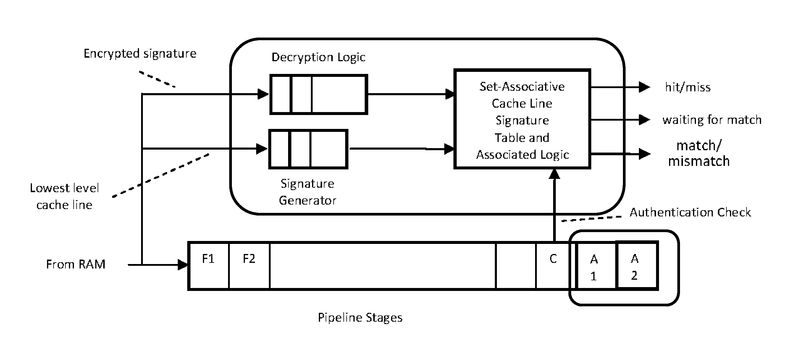
The present invention verifies the authenticity of instructions in a processor cache while the instructions are being executed. This prevents a delay in instruction processing while the verification is occurring, which is beneficial as instruction execution is faster than verification. The invention takes advantage of modern processor architectures to allow for initial stages of program execution to speculatively execute, with a contingent exception or flushing occurring dependent on the verification status, providing the desired security.

Problems solved by technology

Current computer systems are highly vulnerable to cyber attack.
The number of attacks and the financial losses due to those attacks have risen exponentially.
Despite significant investments, the situation continues to worsen; novel attacks appear with high frequency and employ increasingly sophisticated techniques.
These attacks stem from the fact that current computer systems cannot enforce the intended semantics of their computations.
In particular, they fail to systematically enforce: Memory safety, Type safety, The distinction between code and data, and Constraints on information flow and access.
These properties are not systematically enforced today because they are not: Systematically captured during the design process; Formally analyzed or verified during design and implementation; Captured or enforced by common system programming languages (e.g., the C programming language); and Represented explicitly within the runtime environment of the system and therefore cannot be enforced dynamically by either hardware or software techniques.
Current system software is large and complex.
Consequently, a single penetration into the kernel gives the attacker unlimited access.
Since the cost of switching into kernel mode is high, there is a tendency for system programmers to move increasing amounts of functionality into the kernel, making it even less trustworthy and exposing an even larger attack surface.
Likewise, programming flaws can result in unintended access to kernel or increased privilege level system access.
Current computer systems are not resilient to attacks.
They lack the means to recover from attacks either by finding alternative methods for achieving their goals or by repairing the resources corrupted by the attack.
They also typically lack the ability to diagnose the underlying problem and to fix the vulnerabilities that enabled the attack.
Once a machine is corrupted, manual repairs by specialized personnel are required while the forensic information necessary to affect the repair is typically lacking.
A single network-based attack can therefore spread rapidly and affect a very large number of computers.
The Trusted Platform Module is typically part of the supporting chipset for a processor system, and thus its use typically delays execution of instructions by the processor until verification is completed.
Thus, while the TMP provides secure data processing, it does not address insecurities in moving instructions to the processor, and is susceptible to instruction injection type attaches, and likewise introduces significant latencies.
However even where a TPM is used, a key is still vulnerable while a software application that has obtained it from the TPM is using it to perform encryption / decryption operations, as has been illustrated in the case of a cold boot attack.
This verification will fail if a parasitic virus or other malicious code has altered the software.
The trusted hardware device is tamper-resistant, difficult to forge and inaccessible to other functions of the platform.
Following an attempt to execute a secured program, a system management interrupt is generated.
This not only complicates memory management, but complicates debugging executing software as the program code stored in any particular physical memory location might be from any number of different pages with different virtual addresses.
Further, program code loaded into memory need not be stored in the same physical memory location every time, and the actual physical address into which a program instruction is stored is not necessarily unique.
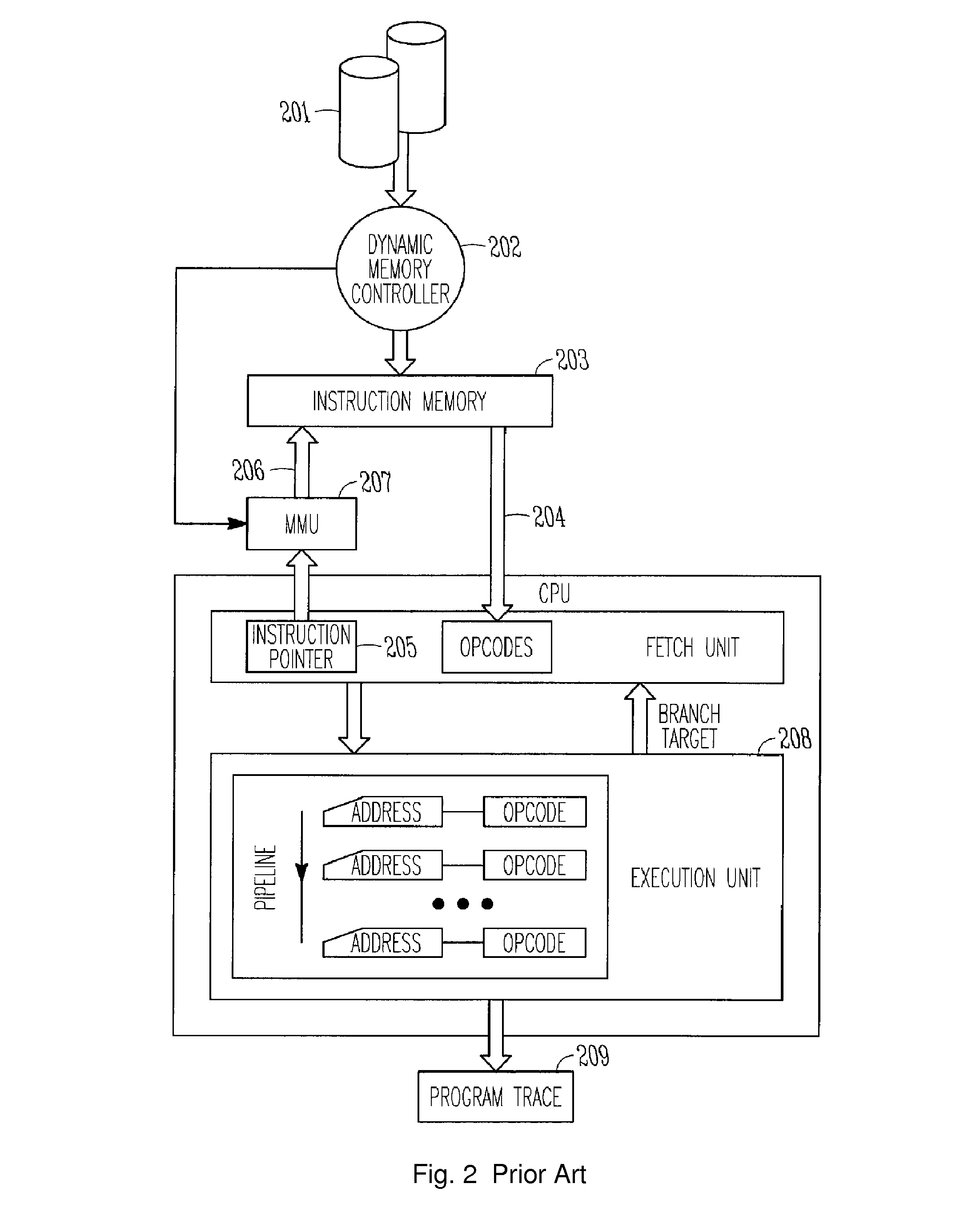
In either case, it can be difficult to later determine which program instructions from storage 201 were present in the virtual or physical address locations recorded, such as when a program has completed execution or has reached a breakpoint in the debugging process.
But, because the address is not necessarily unique to a particular program instruction, false breaks in program execution can occur before the desired breakpoint is reached when using such methods.
This solution is inconvenient if the program is relatively long, as several false program halts can occur before the desired breakpoint is reached.
It remains problematic in applications where the program can't be stopped in certain points, such as in the engine control and industrial process control examples discussed earlier.
This approach becomes impractical when relatively large numbers of pages are swapped in and out of memory, or when the size of data blocks swapped in and out of memory is relatively small.
It is also problematic in that it requires additional logic and synchronization to track loading data into memory, particularly if the data is not loaded by the processor but is loaded by a direct memory access (DMA) controller or another such component.
Although simply recording all instructions executed in order would reveal what code is actually executing, recording all executed instructions would require an undesirably large amount of storage space and is not a practical solution.

Method used


Image

  • System and method for validating program execution at run-time
  • System and method for validating program execution at run-time
  • System and method for validating program execution at run-time

Examples


Embodiment Construction

A. Dynamic Authentication of Executions Using Cache Line Signatures

[0137]An approach for authenticating program execution dynamically is to detect if the binaries of the executables are compromised during the execution. One way to do this is to detect that the instructions that are fetched and executed, as the program is running, are indeed the same instructions that are supposed to be fetched and executed.

[0138]One way to do this is as follows:

[0139]The executable code is broken down into contiguous chunks at the boundaries of the cache lines (say, of size L) at the lowermost on-chip cache level. If necessary, padding can be used at the end of the code to round its size up to a multiple of the cache line size at the lowest level cache. A signature is generated for each such line by simply generating a digest function D on smaller chunks of each such line, for example at 16-bit or 32-bit boundaries. Thus, for each lowest level cache line's worth of code (say, Li), a specific signatu...


PUM


Abstract

A pipelined processor comprising a cache memory system, fetching instructions for execution from a portion of said cache memory system, an instruction commencing processing before a digital signature of the cache line that contained the instruction is verified against a reference signature of the cache line, the verification being done at the point of decoding, dispatching, or committing execution of the instruction, the reference signature being stored in an encrypted form in the processor's memory, and the key for decrypting the said reference signature being stored in a secure storage location. The instruction processing proceeds when the two signatures exactly match and, where further instruction processing is suspended or processing modified on a mismatch of the two said signatures.

Description

CROSS REFERENCE TO RELATED APPLICATIONS[0001]The present application is a non-provisional application of, and claims benefit of priority from, U.S. Provisional Patent Application Ser. No. 61 / 364,795, filed Jul. 15, 2010, the entirety of which is expressly incorporated herein by reference.FIELD OF THE INVENTION[0002]The present invention relates to systems and methods for secure computing.BACKGROUND OF THE INVENTION[0003]Current computer systems are highly vulnerable to cyber attack. The number of attacks and the financial losses due to those attacks have risen exponentially. Despite significant investments, the situation continues to worsen; novel attacks appear with high frequency and employ increasingly sophisticated techniques. There are very few fundamental sources of the vulnerabilities exploited by cyber attackers. These attacks stem from the fact that current computer systems cannot enforce the intended semantics of their computations. In particular, they fail to systematical...

Claims


Application Information

Patent Timeline
IPC IPC(8): G06F11/14G06F21/54G06F9/44G06F11/36G06F21/72G06F9/38
CPCG06F21/72G06F21/54G06F11/1407G06F9/3834G06F11/3612G06F9/3851G06F21/52G06F21/79G06F9/3863G06F21/51
Inventor GHOSE, KANAD
Owner THE RES FOUND OF STATE UNIV OF NEW YORK
Learn More