Biogas purification apparatus and method for operation thereof

a biogas and purification apparatus technology, applied in lighting and heating apparatus, positive displacement liquid engines, separation processes, etc., can solve the problems of affecting the use of biogas as a renewable energy source, affecting the efficiency of biogas production, etc., to achieve the effect of reducing water requirements and high pressure spray

Active Publication Date: 2014-09-09
THE RES FOUND OF STATE UNIV OF NEW YORK
View PDF5 Cites 10 Cited by
  • Summary
  • Abstract
  • Description
  • Claims
  • Application Information

AI Technical Summary

Benefits of technology

[0022]An advantage of the present invention is that a limited amount of water is required and a need for a high pressure spray is avoided to purify biogas. In the present invention, water frozen as clathrate during the biogas purification process is allowed to warm up to release trapped gases such as H2S and CO2. The released gases can be monitored by spectroscopic analysis, such as gas chromatography. The water is then recycled in the next biogas purification cycle. This water re-usage step sharply reduces water requirements for the entire process, making use of the process feasible in regions having limited water supplies.
[0023]An aspect of the present invention is to provide a biogas purification method including injecting biogas into a pressure vessel, cooling the pressure vessel to a first predetermined temperature and pressurizing the pressure vessel to a predetermined pressure. The method further includes visually monitoring separation of a biogas impurity from a product gas during an induction period, isolating the product gas from the biogas impurity at a clathrate formation equilibrium by removing the product gas from the pressure vessel and passing the product gas through water to yield a purified gas.
[0024]In accordance with an aspect of the present invention, a process for separating components of a gaseous mixture includes injecting the gaseous mixture into a pressure vessel, injecting an aqueous solution into the pressure vessel having a predetermined concentration of an anionic surfactant and cooling the pressure vessel to a predetermined temperature pressurizing the pressure vessel to a predetermined pressure. The method further includes visually monitoring separation of a gas impurity from a product gas during an induction period and isolating the product gas from the gas impurity at a clathrate formation equilibrium by removing the product gas from the pressure vessel.
[0025]An aspect of the present invention is to provide a skid-mounted apparatus for biogas purification. The skid-mounted apparatus includes a pressure vessel, a dip tube for injecting biogas into an aqueous solution within the pressure vessel, a site glass for visual monitoring of clathrate formation and a gas outlet for removing a product gas. Visual monitoring of the clathrate formation includes monitoring separation of a biogas impurity from the product gas during a clathrate formation period.

Problems solved by technology

However, current purification methods of biogas substantially add to CH4 production cost and hinder use of biogas as a renewable energy source.
For example, conventional methods that use polymeric membranes of high permeability and selectivity for CO2 / H2S are limited in that they are energy-intensive, cause pollution, require solvent-regeneration, have large space requirements, have high labor costs for control and maintenance, and the corrosive nature of the solvents causes membrane fouling.
Purification by liquefaction is expensive because liquefaction requires extreme conditions, i.e., biogas liquefies at −82.5° C. under 4.75 MPa.
However, two major limitations of biogas purification by water scrubbing are the need for a large amount of water, with such water requirement being prohibitive in areas having scarce water resources, and utilization of water spray under a high pressure of about 1.3 Mpa, typically requiring a steel tower for such spray.
The conventional methods of clathrate formation from biogas described above employ stationary systems, which are impractical for biogas purification since the amount of biogas that is output from landfills, bio digesters, and wastewater treatment plants fluctuates and eventually declines in total amount of biogas output.

Method used


Image

  • Biogas purification apparatus and method for operation thereof
  • Biogas purification apparatus and method for operation thereof
  • Biogas purification apparatus and method for operation thereof

Examples


example 1

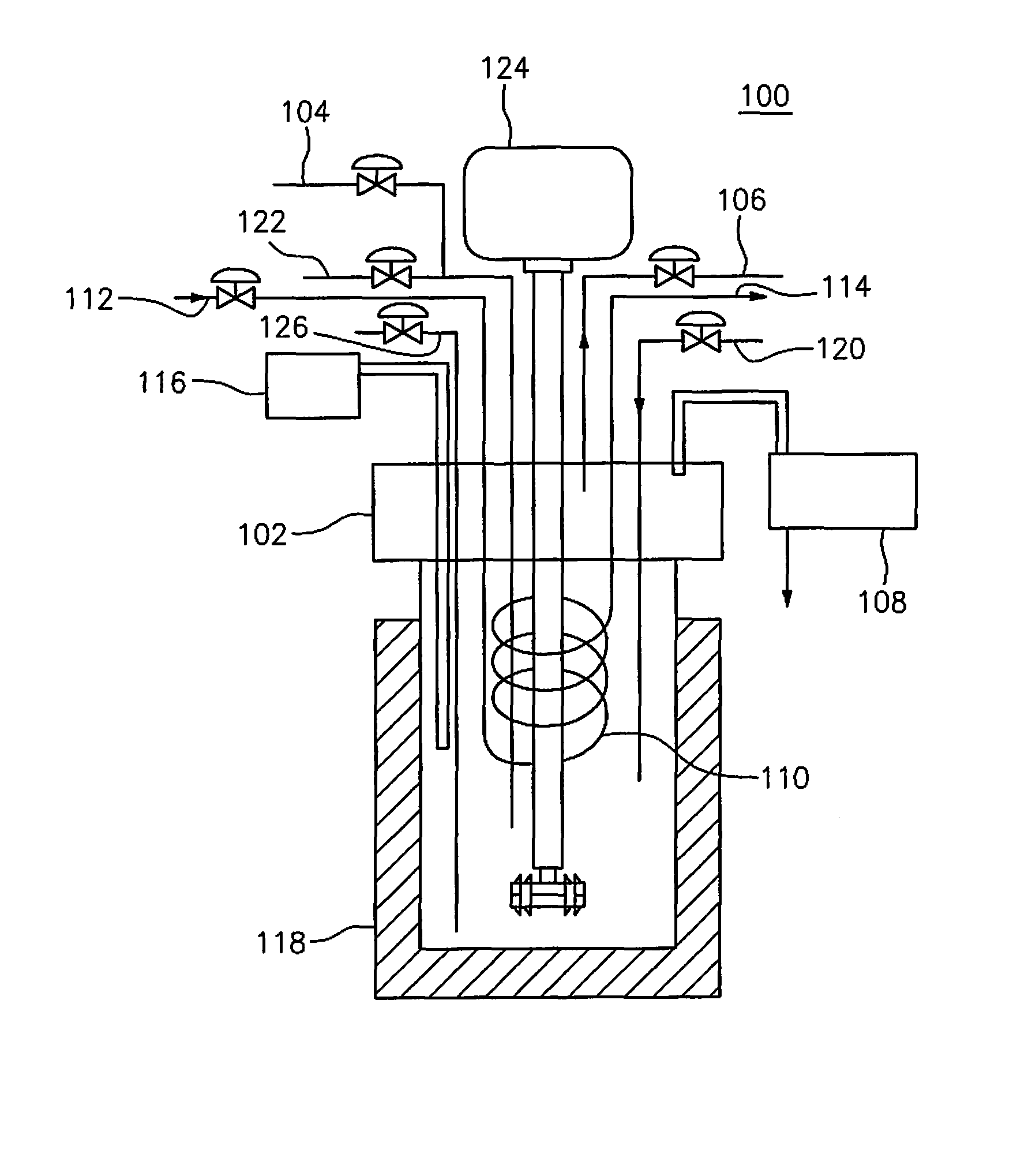
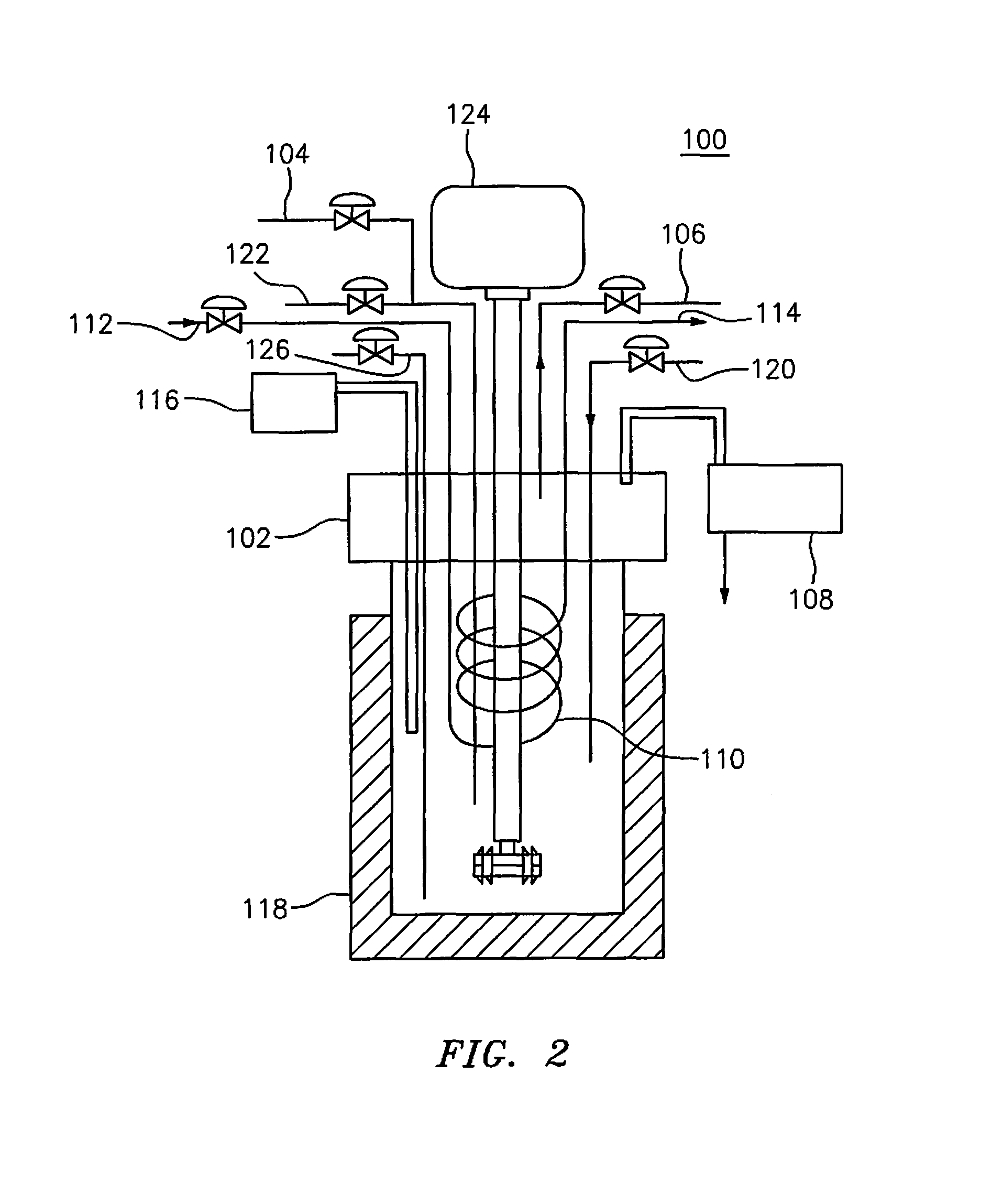
[0047]The pressure vessel 102 is an enclosed 200 mL stainless steel vessel fitted with borosilicate glass windows along a length of the pressure vessel 102. For example, the windows are 1-14 inches long and one inch wide. The pressure vessel 102 can withstand pressures of up to 15 MPa and temperatures as low as −10° C. The windows allow for real time direct visual observation of clathrate formation in the pressure vessel 102 while the biogas purification reaction is in progress. The visualization feature simplifies monitoring of the reaction, and the reaction is generally stopped within 1-30 minutes into the clathrate formation period.

[0048]The pressure vessel 102 is also fitted with the dip tube 126 through which impure biogas enters the vessel. The dip tube 126 extends below the liquid level in the pressure vessel, whereas the gas inlet 104 remains above the liquid level. In the present embodiment, the dip tube 126 forces the entering biogas through an aqeuous solution provided wi...

example 2

[0049]The pressure vessel 102 is initially cooled to between 1° C.-5° C. and biogas is then introduced. Alternatively, an aqueous solution within the pressure vessel 102 is cooled to between 1° C.-5° C. after biogas is introduced to the vessel.

example 3

[0050]The pressure vessel 102 of a 200 mL volume is used. A 75 mL aqueous solution of distilled water and about 0-1000 parts per million (ppm) Sodium Dodecyl Sulphate (SDS), or more preferably 300 ppm of SDS, is injected into the pressure vessel 102 through the liquid / gas inlet 120. The addition of the SDS solution hastens hydrate formation. Then, CO2 gas is gradually bubbled into the SDS solution through the dip tube and the pressure vessel 102 is cooled to a temperature of approximately 2° C.

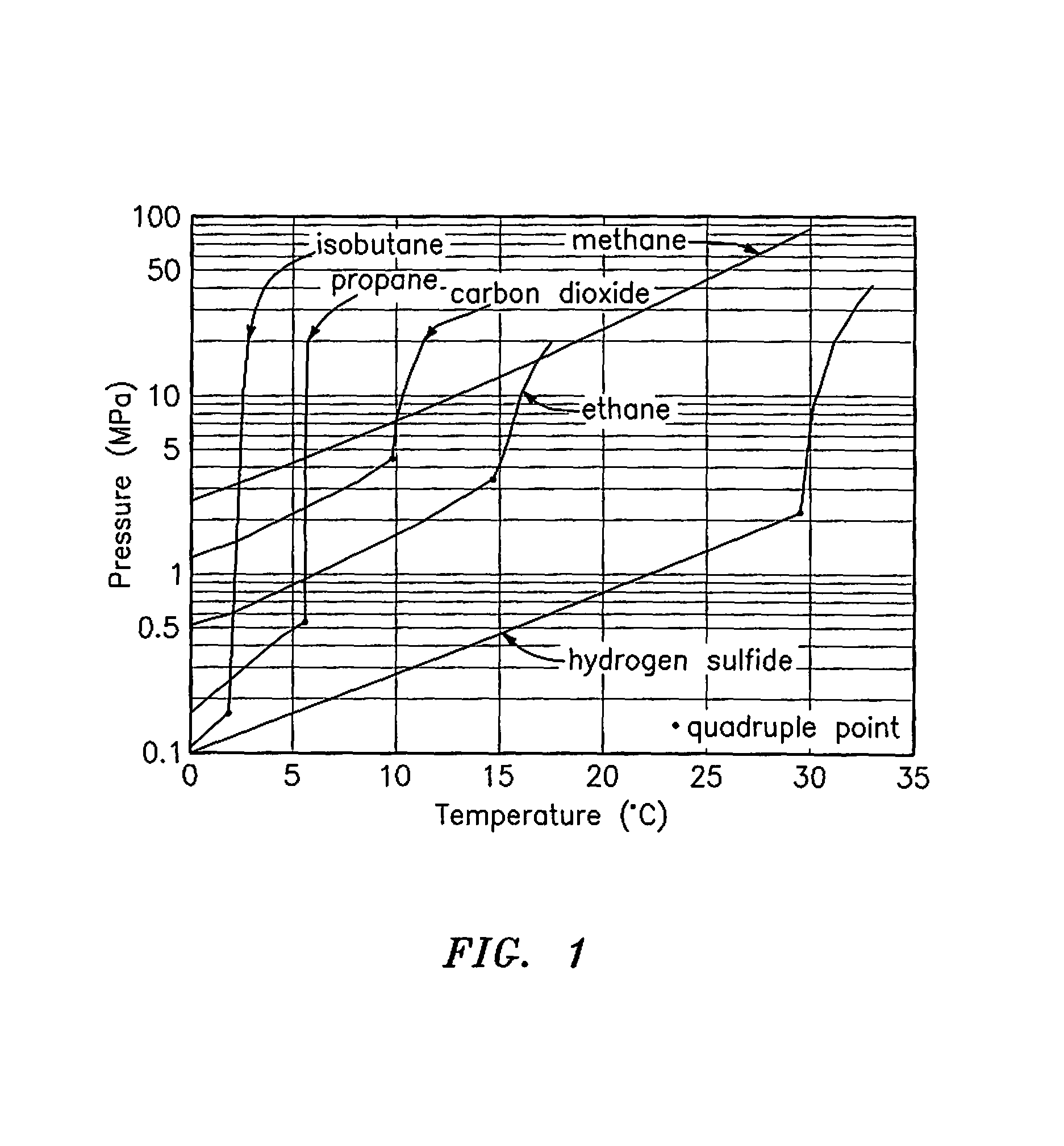
[0051]The pressure and temperature values of the pressure vessel 102, 2° C. and 2 MPa, respectively, along with visual observation, indicate when the separation of the CH4 from the impurities is at a clathrate formation equilibrium, which is the point where hydrate formation stops. Upon reaching equilibrium, white CO2 hydrates accumulate in the aqueous phase, but not at the gas-liquid interface. The liquid interface does not freeze throughout the hydrate formation event, indicating that the hy...


PUM

PropertyMeasurementUnit
temperatureaaaaaaaaaa
pressureaaaaaaaaaa
temperatureaaaaaaaaaa

Abstract

A biogas purification method includes injecting biogas into a pressure vessel, cooling the pressure vessel to a first predetermined temperature and pressurizing the pressure vessel to a predetermined pressure. The method further includes visually monitoring separation of a biogas impurity from a product gas during an induction period, isolating the product gas from the biogas impurity at a clathrate formation equilibrium by removing the product gas from the pressure vessel and passing the product gas through water to yield a purified gas.

Description

PRIORITY[0001]This application claims priority to U.S. Provisional Application No. 61 / 419,583, filed with the U.S. Patent and Trademark Office on Dec. 3, 2010, the contents of which are incorporated herein by reference.BACKGROUND OF THE INVENTION[0002]1. Field of the Invention[0003]The present invention relates to a method and apparatus for biogas purification.[0004]2. Description of the Related Art[0005]Biological transformation of organic material in landfills produces biogas as a result of anaerobic digestion. The organic material includes energy crops, food and farm waste, such as animal manure. Biogas is a mixture of 55-65% methane (CH4), 35-45% carbon dioxide (CO2), and 2-5% nitrogen (N2), with trace amounts of hydrogen sulfide (H2S), carbon monoxide (CO) and water vapor (H2O). CH4 is the main constituent of biogas and is twenty times more potent as a greenhouse gas than CO2. Under normal conditions biogas gas from landfills escapes into the atmosphere and contributes to globa...

Claims


Application Information

Patent Timeline
Patent Type & Authority Patents(United States)
IPC IPC(8): B01D53/00
CPCB01D2257/504B01D2257/304B01D2257/80B01D53/002C10L3/10B01D53/00C10L2290/146C10L3/106C10L2290/06C10L3/108C10L2290/141C10L2290/46C10L3/103C10L3/104C10L2290/143C10L2290/26
Inventor MAHAJAN, DEVINDER
Owner THE RES FOUND OF STATE UNIV OF NEW YORK
Why Eureka
Try Eureka