Hydrocarbon gas processing

a technology of hydrocarbon gas and processing equipment, applied in the direction of refrigeration and liquidation, lighting and heating equipment, solidification, etc., can solve the problems of increasing capital costs, not getting the ideal situation, and not being able to process feed gas

Active Publication Date: 2015-07-14
UOP LLC
View PDF47 Cites 25 Cited by
  • Summary
  • Abstract
  • Description
  • Claims
  • Application Information

AI Technical Summary

Benefits of technology

[0004]The historically cyclic fluctuations in the prices of both natural gas and its natural gas liquid (NGL) constituents have at times reduced the incremental value of ethane, ethylene, propane, propylene, and heavier components as liquid products. This has resulted in a demand for processes that can provide more efficient recoveries of these products, for processes that can provide efficient recoveries with lower capital investment and lower operating costs, and for processes that can be easily adapted or adjusted to vary the recovery of a specific component over a broad range. Available processes for separating these materials include those based upon cooling and refrigeration of gas, oil absorption, and refrigerated oil absorption. Additionally, cryogenic processes have become popular because of the availability of economical equipment that produces power while simultaneously expanding and extracting heat from the gas being processed. Depending upon the pressure of the gas source, the richness (ethane, ethylene, and heavier hydrocarbons content) of the gas, and the desired end products, each of these processes or a combination thereof may be employed.
[0009]The second reason that this ideal situation cannot be obtained is that carbon dioxide contained in the feed gas fractionates in the demethanizer and can build up to concentrations of as much as 5% to 10% or more in the tower even when the feed gas contains less than 1% carbon dioxide. At such high concentrations, formation of solid carbon dioxide can occur depending on temperatures, pressures, and the liquid solubility. It is well known that natural gas streams usually contain carbon dioxide, sometimes in substantial amounts. If the carbon dioxide concentration in the feed gas is high enough, it becomes impossible to process the feed gas as desired due to blockage of the process equipment with solid carbon dioxide (unless carbon dioxide removal equipment is added, which would increase capital cost substantially). The present invention provides a means for generating a supplemental liquid reflux stream that will improve the recovery efficiency for the desired products while simultaneously substantially mitigating the problem of carbon dioxide icing.
[0013]In accordance with the present invention, it has been found that C2 component recoveries in excess of 97 percent can be obtained with no loss in C3+ component recovery. The present invention provides the further advantage of being easily adapted to using much of the equipment required to implement assignee's U.S. Pat. No. 5,799,507, resulting in lower capital investment costs compared to other prior art processes. In addition, the present invention makes possible essentially 100 percent separation of methane and lighter components from the C2 components and heavier components while maintaining the same recovery levels as the prior art and improving the safety factor with respect to the danger of carbon dioxide icing. The present invention, although applicable at lower pressures and warmer temperatures, is particularly advantageous when processing feed gases in the range of 400 to 1500 psia [2,758 to 10,342 kPa(a)] or higher under conditions requiring NGL recovery column overhead temperatures of −50° F. [−46° C.] or colder.

Problems solved by technology

In practice, however, this ideal situation is not obtained for two main reasons.
If the carbon dioxide concentration in the feed gas is high enough, it becomes impossible to process the feed gas as desired due to blockage of the process equipment with solid carbon dioxide (unless carbon dioxide removal equipment is added, which would increase capital cost substantially).
The process and apparatus of U.S. Pat. No. 5,799,507, however, are unsuitable for high ethane recovery.
However, the FIG. 1 process is not well suited to recovering C2 components, as C2 component recovery levels on the order of 40% are generally the highest that can be achieved without inordinate increases in the power requirements for the process.
However, the required modifications require much additional equipment and piping (as shown by the bold lines) and do not make use of much of the equipment present in the FIG. 1 plant (shown by the light dashed lines), so the capital cost of a plant designed to operate using both the FIG. 1 process and the FIG. 2 process will be higher than is desirable.

Method used


Image

  • Hydrocarbon gas processing
  • Hydrocarbon gas processing
  • Hydrocarbon gas processing

Examples


example 1

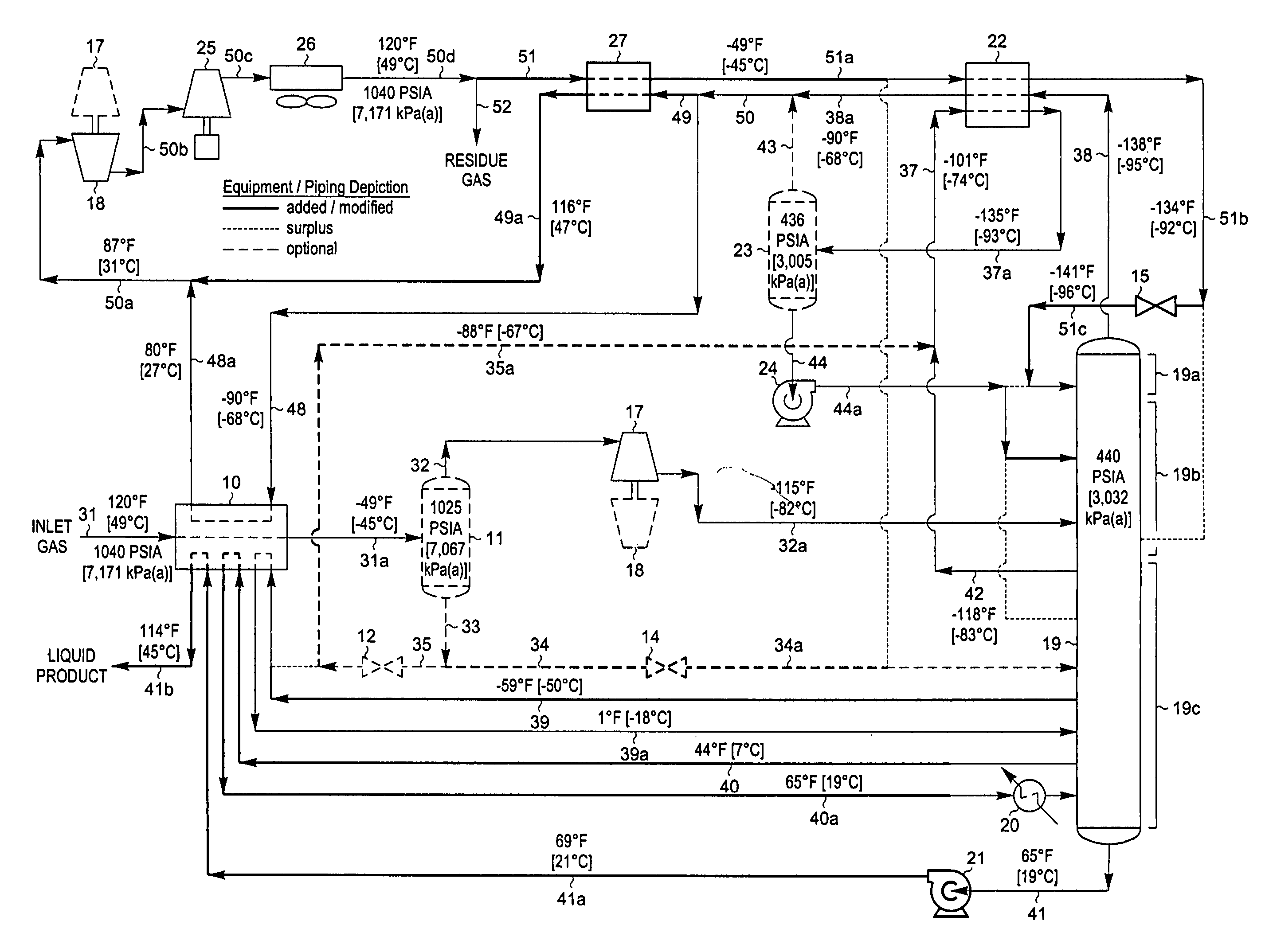
[0046]FIG. 3 is a process flow diagram illustrating how the design of the processing plant in FIG. 1 can be adapted to operate at a higher C2 component recovery level in accordance with the present invention. The process of FIG. 3 has been applied to the same feed gas composition and conditions as described previously for FIG. 1. However, in the simulation of the process of the present invention as shown in FIG. 3, certain equipment and piping have been added (shown by bold lines) while other equipment and piping have been removed from service (shown by light dashed lines) as noted by the legend on FIG. 3 so that the process operating conditions can be adjusted to increase the recovery of C2 components to about 97%. Since the feed gas composition and conditions considered in the process presented in FIG. 3 are the same as those in FIG. 2, the FIG. 3 process can be compared with that of the FIG. 2 process to illustrate the advantages of the present invention.

[0047]In the simulation o...

example 2

[0071]FIG. 3 represents the preferred embodiment of the present invention for the temperature and pressure conditions shown because it typically requires the least equipment and the lowest capital investment. An alternative method of producing the supplemental reflux stream for the column is shown in another embodiment of the present invention as illustrated in FIG. 5. The feed gas composition and conditions considered in the process presented in FIG. 5 are the same as those in FIGS. 1 through 3. Accordingly, FIG. 5 can be compared with the FIG. 2 process to illustrate the advantages of the present invention, and can likewise be compared to the embodiment displayed in FIG. 3.

[0072]In the simulation of the FIG. 5 process, inlet gas enters the plant as stream 31 and is cooled in heat exchanger 10 by heat exchange with a portion (stream 48) of cool distillation stream 38a at −79° F. [−62° C.], demethanizer liquids (stream 39) at −47° F. [−44° C.], demethanizer liquids (stream 40) at 44...


PUM


Abstract

A process for the recovery of ethane, ethylene, propane, propylene, and heavier hydrocarbon components from a hydrocarbon gas stream is disclosed. The stream is cooled and is thereafter expanded to the fractionation tower pressure and supplied to the fractionation tower at a lower mid-column feed position. A distillation stream is withdrawn from the column below the feed point of the stream and is then directed into heat exchange relation with the tower overhead vapor stream to cool the distillation stream and condense at least a part of it, forming a condensed stream. At least a portion of the condensed stream is directed to the fractionation tower at an upper mid-column feed position. A recycle stream is withdrawn from the tower overhead after it has been warmed and compressed. The compressed recycle stream is cooled sufficiently to substantially condense it, and is then expanded to the pressure of the fractionation tower and supplied to the tower at a top column feed position. The quantities and temperatures of the feeds to the fractionation tower are effective to maintain the overhead temperature of the fractionation tower at a temperature whereby the major portion of the desired components is recovered.

Description

BACKGROUND OF THE INVENTION [0001]This invention relates to a process for the separation of a gas containing hydrocarbons. The applicants claim the benefits under Title 35, United States Code, Section 119(e) of prior U.S. Provisional Application No. 60 / 692,126 which was filed on Jun. 20, 2005.[0002]Ethylene, ethane, propylene, propane, and / or heavier hydrocarbons can be recovered from a variety of gases, such as natural gas, refinery gas, and synthetic gas streams obtained from other hydrocarbon materials such as coal, crude oil, naphtha, oil shale, tar sands, and lignite. Natural gas usually has a major proportion of methane and ethane, i.e., methane and ethane together comprise at least 50 mole percent of the gas. The gas also contains relatively lesser amounts of heavier hydrocarbons such as propane, butanes, pentanes, and the like, as well as hydrogen, nitrogen, carbon dioxide, and other gases.[0003]The present invention is generally concerned with the recovery of ethylene, etha...

Claims


Application Information

Patent Timeline
Patent Type & Authority Patents(United States)
IPC IPC(8): F25J3/00F25J3/02
CPCF25J3/0209F25J3/0233F25J3/0238F25J2200/02F25J2200/04F25J2200/70F25J2200/76F25J2200/78F25J2205/02F25J2205/04F25J2220/66F25J2230/08F25J2235/60F25J2240/02F25J2280/02F25J2290/40F25J2290/80F25J2200/30
Inventor PITMAN, RICHARD N.WILKINSON, JOHN D.LYNCH, JOE T.HUDSON, HANK M.CUELLAR, KYLE T.MARTINEZ, TONY L.
Owner UOP LLC
Why Eureka
Try Eureka