
Flexible nonlinear laser scanning microscope for noninvasive three-dimensional detection

a flexible technology, applied in the field of flexible, nonlinear laser scanning microscopes, can solve the problems of no high-resolution imaging systems, lateral resolution of about 1 m or less, known for nonlinear microscopy or tomography, etc., and achieve the effect of unlimited flexibility of the measuring head

Active Publication Date: 2015-11-03
JENLAB
View PDF15 Cites 2 Cited by
  • Summary
  • Abstract
  • Description
  • Claims
  • Application Information

AI Technical Summary

Benefits of technology

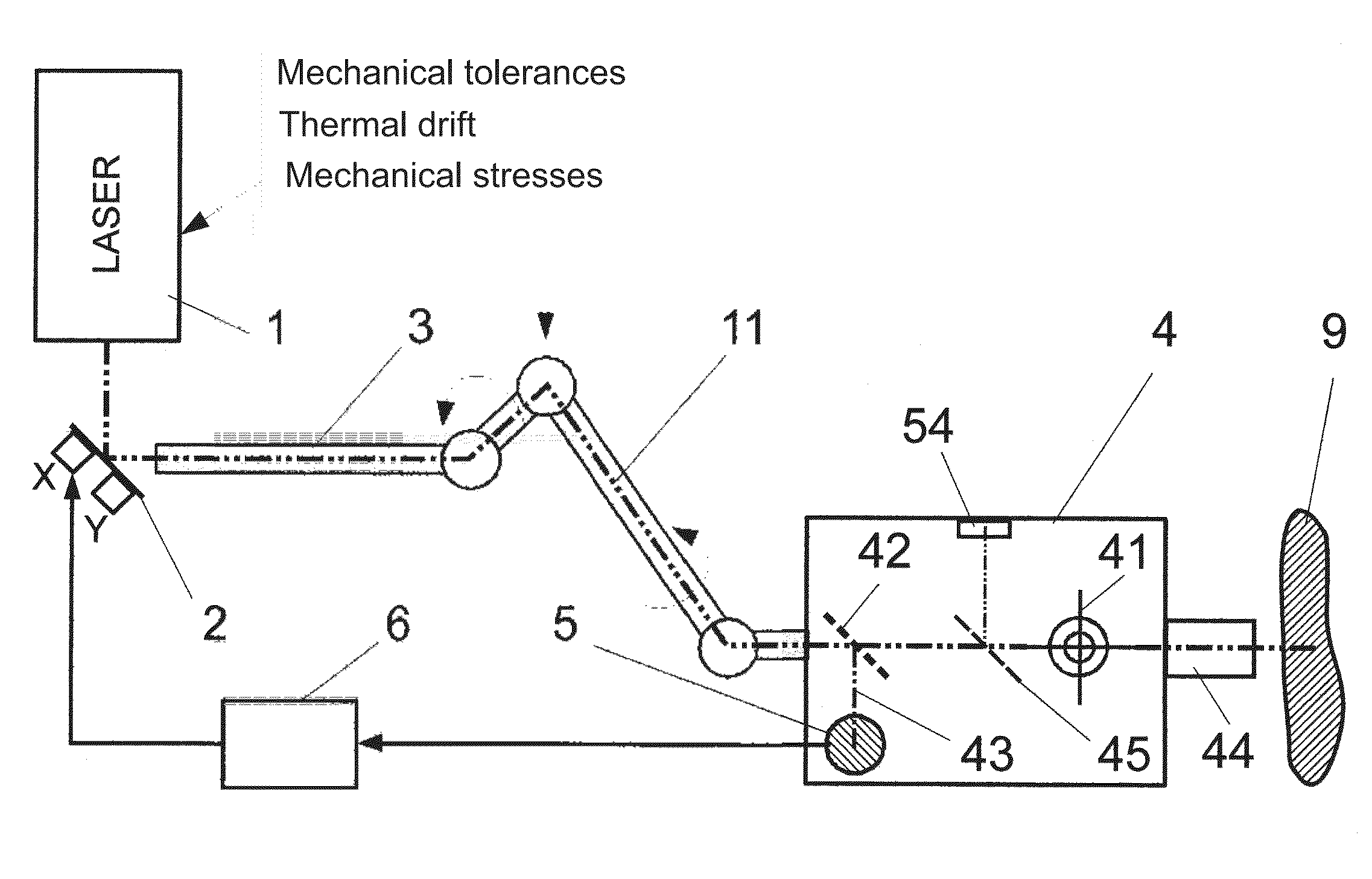
[0015]Therefore, it is the object of the invention to provide a mobile, flexibly usable nonlinear laser scanning microscope for noninvasive three-dimensional detection for multivalent high-resolution nonlinear examinations, particularly of skin, tissue in the urogenital area, in the oral cavity and in the eye area of the human body, but also in plants, animals, cell cultures and in nonliving material, which permits a reproducible illumination of the focusing optics with unlimited flexibility of the measuring head. An extended object is to realize a reproducibly convergent, simultaneous application of two beam paths for purposes of combining different measuring methods, preferably MP tomography and CARS tomography, in a shared flexible measuring head.
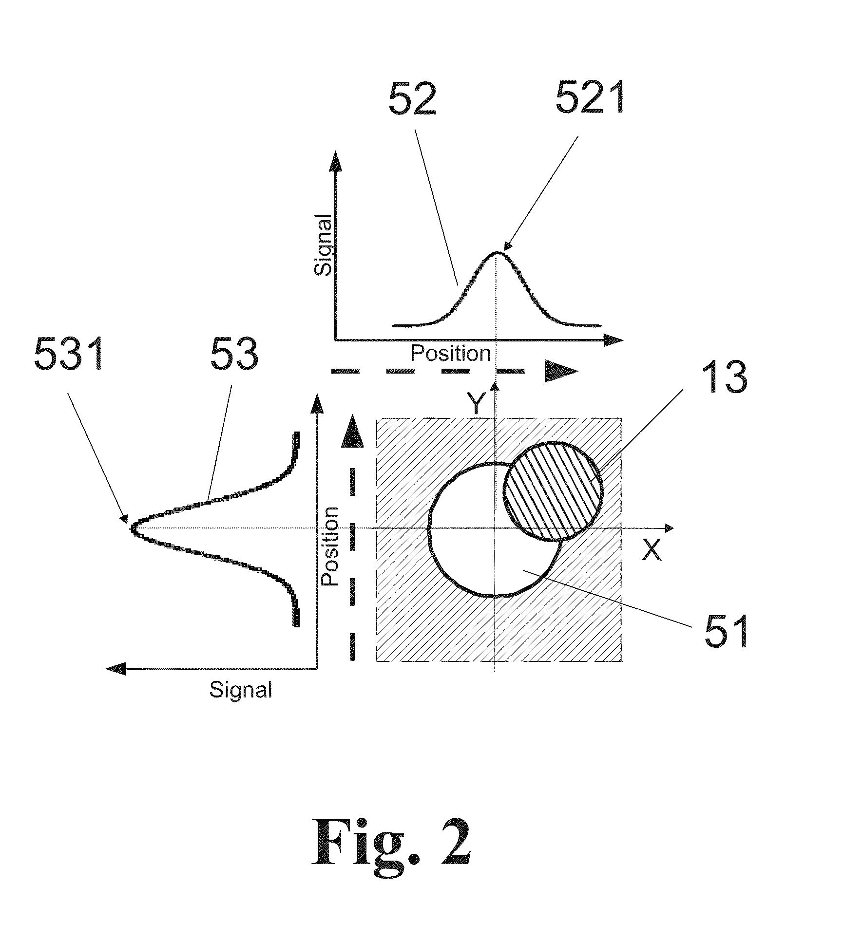
[0023]In addition to controlling the beam stability in the transmission optics, the position-sensitive photodetector can also advantageously determine and correct the pointing stability of the laser.
[0024]The detector system for the secondary radiation emitted from the measurement object is preferably constructed with a detector for MPT imaging or SHG imaging so as to provide a flexible diagnostic system for fluorescing substances which permits free positioning of the measuring head in space by means of a flexible optical articulated arm of low mechanical accuracy and ensures a reproducible MPT imaging.
[0025]The detector system for the secondary radiation can be formed in a particularly advantageous manner with a plurality of detectors for MPT imaging, SHG imaging and CARS imaging so as to provide a flexible diagnostic system for fluorescing and nonfluorescing substances in living matter which by means of a shared flexible optical articulated arm permits any free positioning of the shared measuring head in space and generates a simultaneous, co-located imaging from MPT signals, SHG signals and CARS signals. In so doing, the diagnostic system which is combined in this way for fluorescing and nonfluorescing substances can also conveniently permit the free positioning of the shared measuring head via a flexible optical articulated arm and a separate optical fiber. Further, it is possible to realize a free positioning of the shared measuring head for simultaneous, co-located imaging in the flexible combined diagnostic system by means of two separate optical fibers.
[0030]The invention meets these divergent requirements with a technologically simple, cost-effective and compact directional stabilization for laser radiation (or incoherent radiation) having for purposes of minimizing deviations a detector, a control unit and an actuator. Depending on the detected deviation in a conjugate target plane within an unrestrictedly flexible measuring head, a correction of the beam direction of the laser beam is carried out by means of the control unit (simple logic circuit) before this laser beam is coupled into the illumination and recording system (focusing optics) of the measuring head. At the same time, this beam stabilization also ensures the collinearity of the measurement radiation when a plurality of excitation beams are used.
[0031]Accordingly, the requirements imposed on a mechanical cage structure of an articulated mirror arm with regard to the required accuracy of the beam guidance are reduced and the resulting savings on volume and weight comply with the flexibility and mobility of the microscope measuring system (e.g., a tomograph). Advantages of the directional stabilization, e.g., compact, small-sized construction and cost effectiveness, are evidenced particularly in the fiber coupling input in fiber transmission systems.

Problems solved by technology

However, no high-resolution imaging systems (with a lateral resolution of about 1 μm or less) permitting a free positioning of the measuring head at the required lateral and axial resolution in the submicrometer range are known for nonlinear microscopy or tomography.
While the deviations to be compensated in guiding the laser beam are reduced exclusively to the in-coupling and out-coupling of the beam when using fiber transmission optics, the basic problem of undesirable laser beam deviation at the target site remains.
In particular, there is also the risk of unwanted coupling into the fiber sheath (cladding).
Further, an overlapping illumination of the fiber input (i.e., beam diameter greater than fiber diameter) is required and, therefore, a loss of intensity is already inevitable from the outset.
Accordingly, the prior art presents the following disadvantages:owing to their rigid construction, conventional two-photon microscopes and multiphoton tomographs (MPTs) present a limited range of application and are, for example, unsuitable for multifunctional examinations on the human body;for realizing a flexible construction, the mechanical tolerances of beam-guiding systems are too large to ensure a sufficiently constant illumination of a measurement spot for a reproducible irradiation of the scan site permitting a submicrometer resolution; andin multiphoton microscopy, the limitation of imaging to the detection of autofluorescence of endogenous substances and to nonlinear frequency multiplication of certain molecules is often disadvantageous, and the desirable combination with CARS systems could only be realized heretofore in rigid systems because of the strict requirements respecting collinearity.

Method used


Image

  • Flexible nonlinear laser scanning microscope for noninvasive three-dimensional detection
  • Flexible nonlinear laser scanning microscope for noninvasive three-dimensional detection
  • Flexible nonlinear laser scanning microscope for noninvasive three-dimensional detection

Examples


embodiment example 1

[0057]As is shown in FIG. 3, the measurement system is a mobile, flexible nonlinear scanning microscope comprising a mobile base device 7 on wheels for freely selectable positioning. A measuring head 4 which is freely movable in space is attached to this base device by a supporting arm 8. Further, two different optical transmission optics 3, an articulated mirror arm 31 and an optical fiber 32, are arranged between the base device 7 and the measuring head 4 for optically guiding the laser radiation needed for the imaging laser scanning. They are provided for transmission of the excitation radiation for different detection methods, for example, and without limiting generality, for multiphoton tomography and CARS tomography, wherein the different excitation beams are superposed collinearly in the measuring head 4. To this end, the system for beam stabilization shown schematically in FIG. 1 with position-sensitive photodetector 5, control unit 6 and controllable tilt mirror 2 is used i...

embodiment example 2

[0059]As was described above referring to FIG. 3, the microscope according to the invention shown in FIG. 4 comprises a mobile base device 7 on wheels for freely selectable positioning.

[0060]For multiphoton imaging, there are provided in the base device 7 a short-pulse laser system 71 (5 fs-500 ps; with Gaussian beam profile, e.g., a titanium:sapphire laser) and an optical unit 72 in which the controllable tilt mirror 2 as two-axis tilt mirror 21 couples the laser beam 11 coming from the short-pulse laser system 71 into flexible transmission optics 3 in the form of an articulated mirror arm 31. In this first example, the laser beam 11 is guided to the optical measuring head 4 via the flexible articulated mirror arm 31. A movable supporting arm 8 which comprises a plurality of parts and can be locked in any position allows the optical measuring head 4 to be freely positioned so that the articulated mirror arm 31 is positively driven in a corresponding manner. Therefore, the measuring...

embodiment example 3

[0070]FIG. 5 shows the measuring system using an articulated mirror arm 31 and an optical fiber 32 as two separate beam-guiding optical transmission systems 3.

[0071]In the same way as in the second example, the short-pulse laser 71 is coupled into the flexible articulated mirror arm 31 by the optical unit 72 via the two-axis tilt mirror 21 and is guided to the optical measuring head 4.

[0072]The frequency conversion unit 73 used for generating the additional CARS imaging is provided with the output wavelength generated by the short-pulse laser 71 by means of the laser beam 11′ coupled out of the beamsplitter 725 via a deflecting mirror 721 and emits a laser beam 12 with a wavelength deviating from the short-pulse laser 71. In contrast to the previous example, after initially traversing the telescope system 722, the laser beam 12 is then aligned separately in two coordinate directions before the optical delay line 723 by means of a first single-axis tilt mirror 23 and a second single-...


PUM

PropertyMeasurementUnit
angleaaaaaaaaaa
flexibleaaaaaaaaaa
nonlinear laser scanning microscopeaaaaaaaaaa

Abstract

A nonlinear laser scanning microscope for flexible, noninvasive three-dimensional detection comprising a measuring head which is flexibly connected to at least one radiation source by transmission optics and can be freely positioned in space, at least one controllable tilt mirror is arranged for aligning the excitation beam in order to keep the excitation beam concentric to an aperture-limited optical element of the measuring head, a test beam which is coupled out of the excitation beam onto a spatially resolving photodetector for monitoring the center alignment of the test beam as a conjugate position to the target position of the excitation beam and directional stabilizing the excitation beam by a control unit of the tilt mirror depending on a determined deviation.

Description

FIELD OF THE INVENTION[0001]The invention is directed to a nonlinear laser scanning microscope for flexible, noninvasive three-dimensional detection, particularly in living matter (in vivo), preferably in the skin of animals, in plants and cell cultures, and in nonliving matter such as, for example, minerals, textiles and works of art. By nonlinear laser scanning microscope or microscope with multiphoton (MP) excitation is always meant hereinafter a microscope having two-photon or multiphoton excitation.BACKGROUND OF THE INVENTION[0002]Two-photon microscopes and multiphoton tomographs (MPT) in which fluorescence signals and SHG (Second Harmonic Generation) signals are excited in biological molecules in vivo by pulsed laser radiation in the near infrared region and are detected by suitable highly sensitive, fast receivers are known (e.g., U.S. Pat. No. 5,034,613 A, DE 201 17 294 U1; DE 203 06 122 U1). Further, nonfluorescing and non-SHG active components such as water and lipids can ...

Claims


Application Information

Patent Timeline
Patent Type & Authority Patents(United States)
IPC IPC(8): G01N21/00G02B21/00G01B11/30G01J3/52A61B5/00
CPCG02B21/0032A61B5/0068G02B21/0028G02B21/0076A61B5/6835A61B2560/0437G01J1/4257G01J2001/4238
Inventor KOENIG, KARSTENWEINIGEL, MARTIN
Owner JENLAB
Learn More