
Low focal shift kW class optical isolator

a technology of optical isolators and low focal shift, which is applied in the field of low-frequency optical isolators, can solve the problems of unstable laser running, irreparable damage to the laser itself, and thermal effects of optical isolators suitable for use with high-power lasers, so as to reduce thermal birefringence, facilitate use, and preserve the effect of highly stable beam parameters

Active Publication Date: 2016-02-23
ELECTRO OPTICS TECH
View PDF14 Cites 4 Cited by
  • Summary
  • Abstract
  • Description
  • Claims
  • Application Information

AI Technical Summary

Benefits of technology

This approach substantially eliminates focal shifts and thermal birefringence, enabling high isolation at power levels beyond 1 kW, maintaining stable beam parameters, and is suitable for high power fiber lasers and diode arrays.

Problems solved by technology

These reflections can cause the laser to run unstable or, in extreme cases, irreparably damage the laser itself.
To date, optical isolators suitable for use with high power lasers have suffered from thermal effects within the isolator optical elements.
Stress birefringence and end effects also contribute to the thermal lens, however, since their contribution is small they are usually ignored.
For this reason, past attempts to reduce the focal length of the thermal lens have used large beams in very large and expensive Faraday rotators.
Although a larger beam size due to such focal shift may be suitable for building up bulk interior sections of a part, it will be unable to sinter fine features and accurate surfaces quickly at high power.
Hence, such large thermal lens focal shifts will generally require the power to be kept very low for all fine features and accurate surfaces, making the time to build a typical part impractically long.
This is just one example of the numerous ways thermal focal shift due to thermal lensing in optical isolators can be unsuitable for industrial application.
The other detrimental thermal effect occurring in high power isolators noted previously is thermal birefringence.
This thermal birefringence becomes the limiting factor determining the isolation ratio, and consequently the effectiveness, of an optical isolator at high power.
However, due to the strong wavelength dependence of the desired 22.5° Faraday rotation angle in the method above, this birefringence compensation method alone does not achieve high levels of isolation over broad wavelength ranges typical of the gain bandwidth of common high power fiber lasers (as much as 200 nm including Raman gain) or high power fiber coupled laser diode arrays using spectral beam combining.
However, the Verdet constant and thermo-optic improvements that these materials offer relative to TGG are incremental.
Such a reduction in thermal lens focal shift is insufficient to make low thermal lens focal shift, kW class optical isolators of simple construction similar to presently available lower power TGG optical isolators.
Further, new Faraday rotator materials such as TAG in crystalline or transparent ceramic form are difficult and expensive to bring to the market.
Although reduced in magnitude, a cylindrical thermal lens is formed which can be more difficult to focus properly in an optical system.
Additionally, either expensive cylindrical lens systems that are subject to additional thermal lens considerations, or complicated off axis spherical mirror systems prone to aberration at the desired high aspect ratios are required to first convert conventional circular beams to a highly elliptical beam and then back to a circular beam as desired by conventional laser use.
However, the factors noted above have kept slab geometries from being broadly employed with conventional circular beam high power laser sources.
Due to the cost and complexity of multiple optical elements and coolant systems required, such designs have not been employed beyond research lab environments to date and do not appear destined for practical industrial usage.
However this approach has been found to have some major drawbacks.
First, these materials have different thermal conductivity, heat capacity and absorption coefficients, rendering thermal lensing compensation difficult to achieve with dynamic changes in laser power.
Second, negative dn / dT materials typically have strong thermal birefringence, such that the resultant poor extinction defeats the original purpose of the optical isolator.
Finally, most negative dn / dT materials studied to date have undesirable material properties such as low resistance to thermal shock and / or sensitivity to humid environments.
To date, negative dn / dT materials to compensate thermal tensing have not found usage in industrial environments.
However, a compact, robust, inexpensive means for accurately sensing thermal lens focal length shifts to feedback into an active thermal lens compensation system is a difficult design task.
Additionally, the need for sub-Hz response times for rapid power changes while simultaneously precisely maintaining the original beam path is challenging, bulky and costly although future innovation may address these issues.
As a consequence, thermal lensing would not be expected from all-fiber isolators if the Faraday fiber and polarizing fiber which are fusion spliced together in such devices can be made to handle high power.
These research efforts however have been plagued by very large, heavy and expensive magnet structures that do not seem suitable for widespread commercial use.
The effects of thermal birefringence in all-fiber optical isolators are difficult to assess presently, and represent an additional uncertainty at this point in time regarding the potential for high power operation of all-fiber isolators.
As the optic diameter is reduced relative to beam size, spherical aberration increases, causing degradation in beam quality.

Method used


Image

  • Low focal shift kW class optical isolator
  • Low focal shift kW class optical isolator
  • Low focal shift kW class optical isolator

Examples


Embodiment Construction

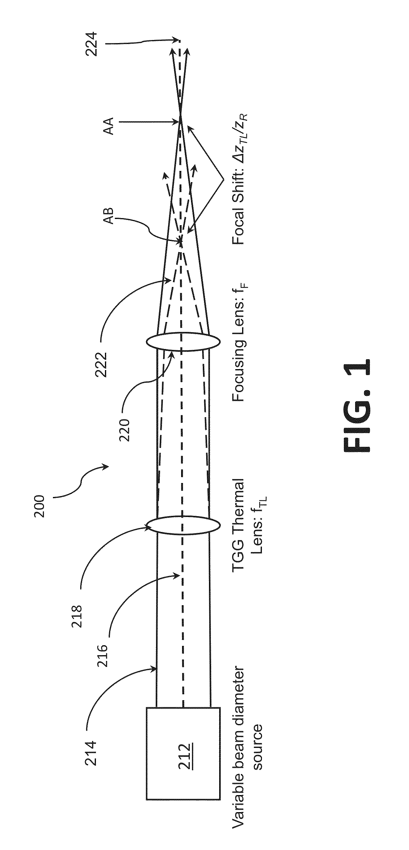
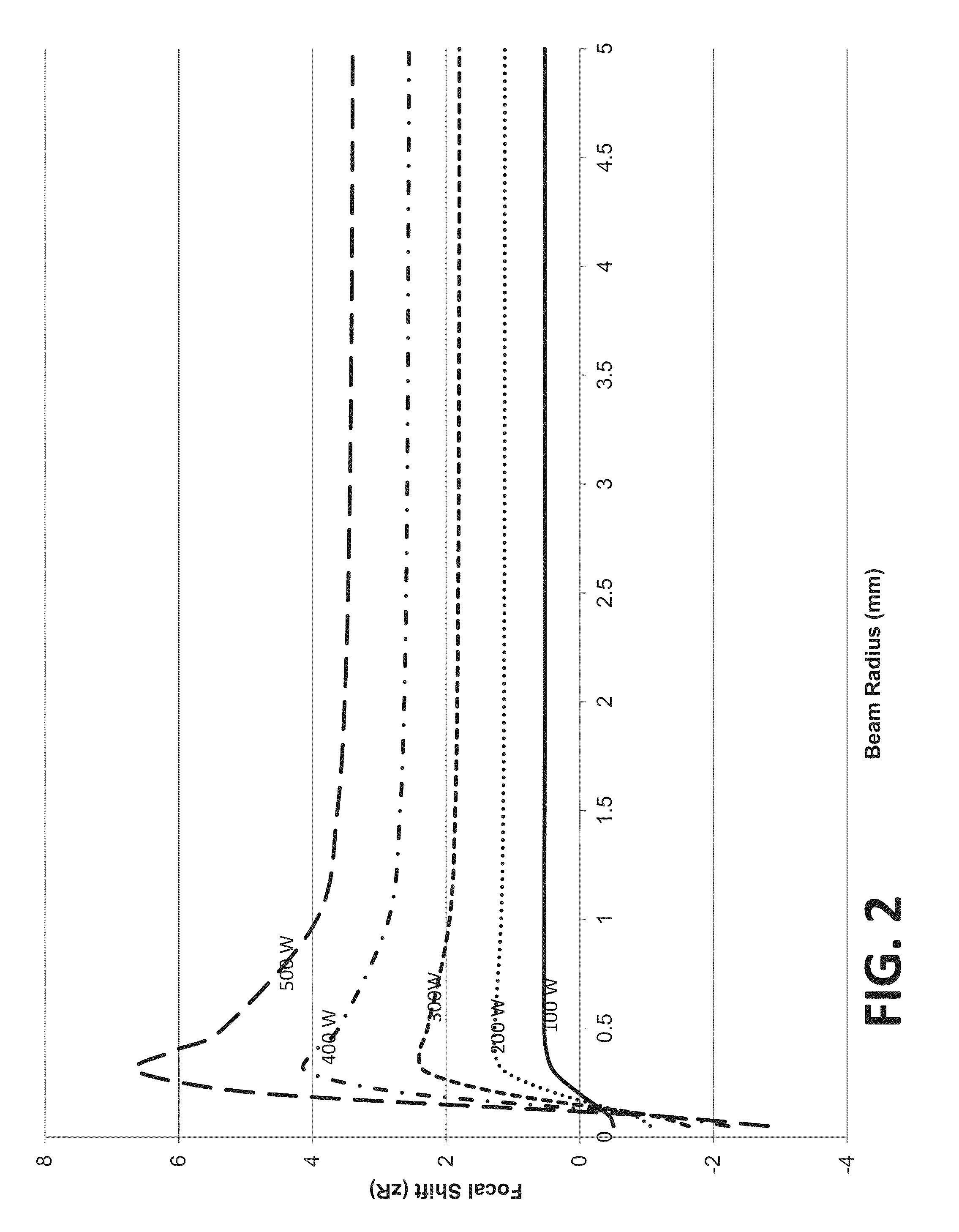
[0051]The invention can best be understood by considering focal shifts due to thermal tensing versus incident power when varying the collimated beam radius at the thermal lens. FIG. 1 illustrates an optical system 200 (prior art) modeled using the ABCD matrix method and Gaussian beams. A beam source 212 produces an optical beam 214 of variable diameter that has a central axis 216. The beam 214 is directed on a path along the central axis 216 through a thermal lens 218, such as formed of terbium gallium garnet (TGG), and a focusing lens 220, with a resultant high power ray path 222 and low power ray path 224 characterized by a focal shift from Point AA to Point AB along the central axis 214 upon increased power (with resultant heating effects).

[0052]The TGG thermal lens 18 can be modeled after the methods routinely used for solid-state lasers using known values typical for TGG. The resulting thermal lens focal length as a function of power is then modeled as a paraxial thin lens in a...


PUM

PropertyMeasurementUnit
poweraaaaaaaaaa
diameteraaaaaaaaaa
diameteraaaaaaaaaa

Abstract

A kW Class optical isolator employs negative feedback to yield low focal shift over dynamically changing power levels. The isolator is useful as a kW fiber laser output isolator.

Description

CROSS-REFERENCES TO RELATED APPLICATIONS[0001]This application claims benefit under 35 U.S.C. §119ε to application Ser. No. 61 / 735,421 filed Dec. 10, 2012 and Ser. No. 61 / 736,733 filed Dec. 13, 2012. In addition to patent applications from which priority is claimed, the present application incorporates by reference U.S. patent application Ser. No. 13 / 673,755 filed Nov. 9, 2012.STATEMENT AS TO RIGHTS TO INVENTIONS MADE UNDER FEDERALLY SPONSORED RESEARCH AND DEVELOPMENT[0002]Not applicableREFERENCE TO A “SEQUENCE LISTING,” A TABLE, OR A COMPUTER PROGRAM LISTING APPENDIX SUBMITTED ON A COMPACT DISK[0003]Not applicable.BACKGROUND OF THE INVENTION[0004]This invention relates generally to optical isolators for use with lasers at power levels up to and in excess of 1 kW.[0005]High power optical isolators have been long sought for use with industrial metal working lasers to protect them from deleterious reflections. Highly reflective molten metal pools produced by these lasers can couple re...

Claims


Application Information

Patent Timeline
Patent Type & Authority Patents(United States)
IPC IPC(8): G02F1/09G02B6/42G02B27/28
CPCG02F1/093G02B6/4208G02B6/4296
Inventor ROGERS, EVAN M.JALALI, AMIR A.SCERBAK, DAVID G.
Owner ELECTRO OPTICS TECH
Learn More