Method and system for long-range adaptive mobile beam-forming ad-hoc communication system with integrated positioning

a communication system and adaptive technology, applied in the field of system and method, can solve the problems of limited processing power, limited current consumption and manufacturing cost, limited available space for antenna elements, and reduced efficiency of both mimo techniques and bandwidth efficiency, and satellite systems also suffer from additional atmospheric losses and dispersion effects

Active Publication Date: 2016-12-06
RADIONOR COMM
View PDF10 Cites 35 Cited by
  • Summary
  • Abstract
  • Description
  • Claims
  • Application Information

AI Technical Summary

Benefits of technology

[0019]More specifically, disclosed is a method and system for providing a long range communication network for mobile applications where the offered bandwidth is high, the frequency re-use and network efficiency is high. The communication range is long according to the disclosure as a combination of modulation technique, analog implementation, digital spatial-time signal processing and method of utilization of a highly directive adaptive array symmetrical antenna system. The implementation of a communication controller provides a very high efficiency for both short and long range. The mesh network is organized so no base station is required, and is self-organized so traffic collisions and interference is avoided, and transmission can be done with low latency and jitter.
[0059]The disclosed system and method provide a digital data streaming cluster architecture with concentrators where data is aggregated in concentrator nodes and sent through high-speed data busses. The high-speed bus system has a distributed error handling system that is able to limit the loss of functionality if a cluster unit or hardware line in the high-speed bus suffers from an error condition. The high-speed bus system is arranged as a plurality of single-wire serial data lines where a limited number of logical data channels are dedicated for each physical connection line. In conventional high-speed bus designs, failure of a connection line in bus will halt the bus operation. According to the disclosure, failure of one of the single-wire transmission lines will limit the consequence to loss of a limited number of logical channels. The high-speed bus system detects errors using a built-in error detection mechanism for each single-wire line, and reports which logical channels that are operating and logical channels with transmission errors.

Problems solved by technology

In the context of RF bandwidth efficiency it is not optimum to combine short rage traffic with long range traffic because the communication parameters are optimized for a given range of time-of-flight, and hence, different cell sizes are combined from pico-cells to macro-cells.
For the client terminal, the available space for antenna elements, available processing power, current consumption and manufacturing cost is limited, and the number of antenna elements is typically in a typical range of 2-3 elements.
For mobile applications at longer ranges, the channel changes rapidly causing large channel dispersion, and hence the efficiency of both MIMO techniques and bandwidth efficiency is severely reduced when the terminal is moving.
The satellite systems also suffer from additional atmospheric losses and dispersion effects for terminals close to the poles of the earth, due to the inclination angle is low.
The impact of the atmospheric losses and dispersion effects is known to result in partial unstable links.
Another main limitation with satellite systems are the long delays because of the long distance to the satellite.
For applications, such as voice and video conferencing and real-time remote control applications, this delay reduces the quality of service, link efficiency and also excludes real-time applications that requires short latency time in order to operate properly.
Sensor systems for guidance involving GPS have a limited update speed and a limited vertical resolution in some satellite constellations that limits the performance for high speed guiding systems.
Satellite positioning services, such as GPS, could also easily be disrupted by jamming transmitters which is a severe limitation of secure operation.
Optical systems are fast, precise and difficult to disrupt by jamming, but cannot operate at long distances in unfavorable weather conditions, such as snow, rain and fog.
With prior art combination of different sensor systems and communication systems that must be applied to implement a real-time guidance system for mobile units, this will introduce extra latency and complexity increasing regulation loop delay and reduced stability margins.
The system requires a secondary radio system which is complex and expensive in addition to a very precise direction sensor system in order to determine the optimum direction for the phased array antenna system.
The speed of the mobile units and number of units in the network are limited by the network capacity of the first antenna system which is transmitting omnidirectional at a relatively low data rate.
The system is complex and if the system has many nodes in the network, the latency of mobility information distribution will be significant.
If the RF channel is rapidly changing and the optimum antenna direction is not the direct line-of-sight to the mobile station, the described system will have significant limitations with respect to reliability and range.
The publication does not describe a symmetrical array antenna solution for both the ground station and the aircraft, and limits the frequency re-use for the elevated mobile stations that does not incorporate narrow, adaptive antenna beams.
If the delay spread is short, the numerous multipath copies of the signal cannot be separated using the disclosed correlation method.
The utilization of the disclosed UWB circuitry has other major disadvantages, such as large current consumption, high-speed analog to digital converters with limited dynamic range and because the RF bandwidth is very large, the allowed transmission output power and operative range is very limited.
For non-line of sight applications this method is not feasible because the direction vary very rapidly.
For line of sight applications, the method limits the useable bandwidth if a beam lock is lost, and the receiver needs to re-lock the antenna beam in the receiver.
In tactical scenarios, power emissions into hazard areas or areas with hostile forces operating can be also be limited accordingly.
In both cases the antenna feed point represents a potential dangerous area with respect to radiation.
For long range systems, long time delays for multi-paths is a severe limitation causing inter-symbol interference and requirement for higher encoding gain in modulation, resulting in the loss of data throughput.
For long range communication in ducting combined with reflective surfaces, a delay spread of the signal will degrade the possible data throughput.
In conventional high-speed bus designs, failure of a connection line in bus will halt the bus operation.
According to the disclosure, failure of one of the single-wire transmission lines will limit the consequence to loss of a limited number of logical channels.

Method used


Image

  • Method and system for long-range adaptive mobile beam-forming ad-hoc communication system with integrated positioning
  • Method and system for long-range adaptive mobile beam-forming ad-hoc communication system with integrated positioning
  • Method and system for long-range adaptive mobile beam-forming ad-hoc communication system with integrated positioning

Examples


Embodiment Construction

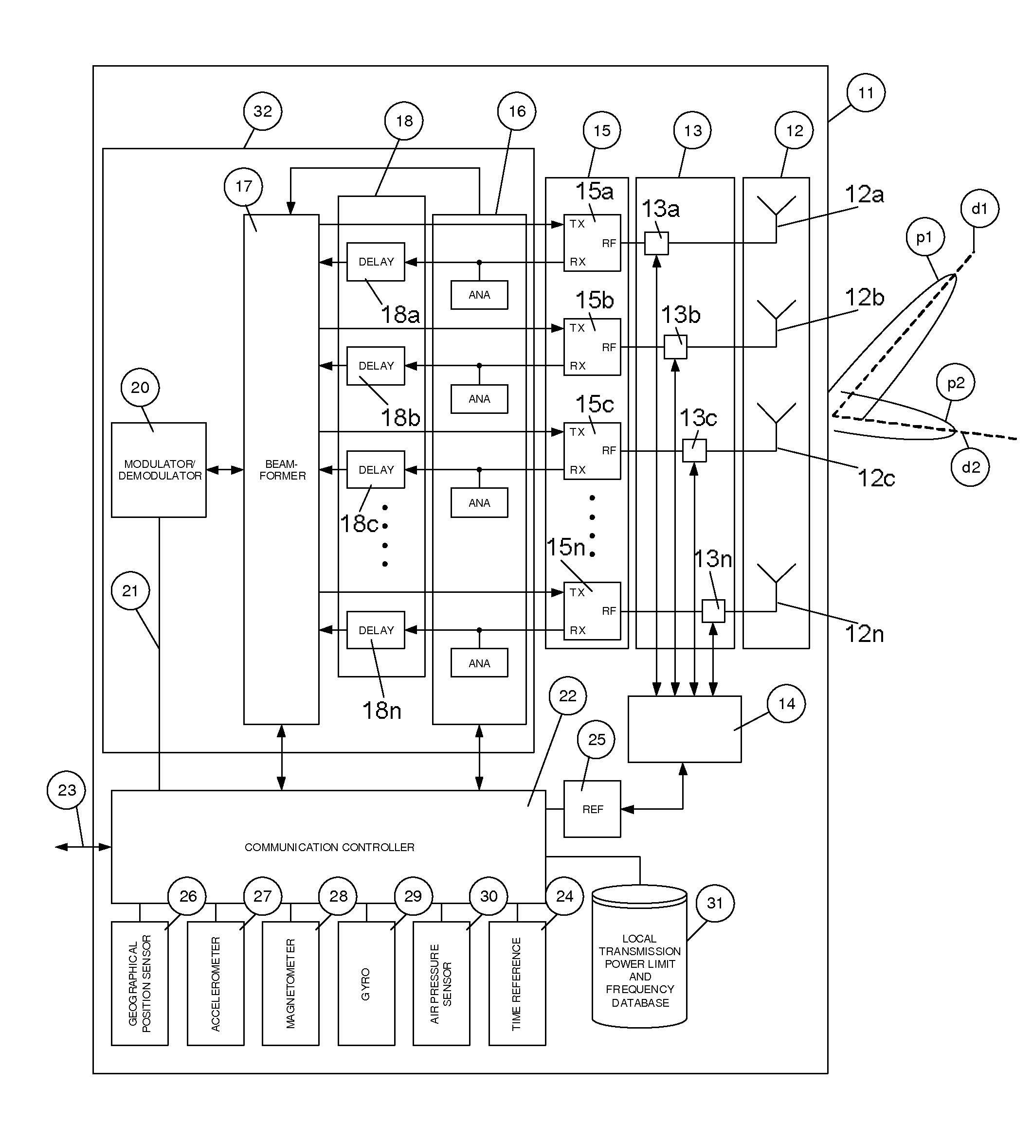
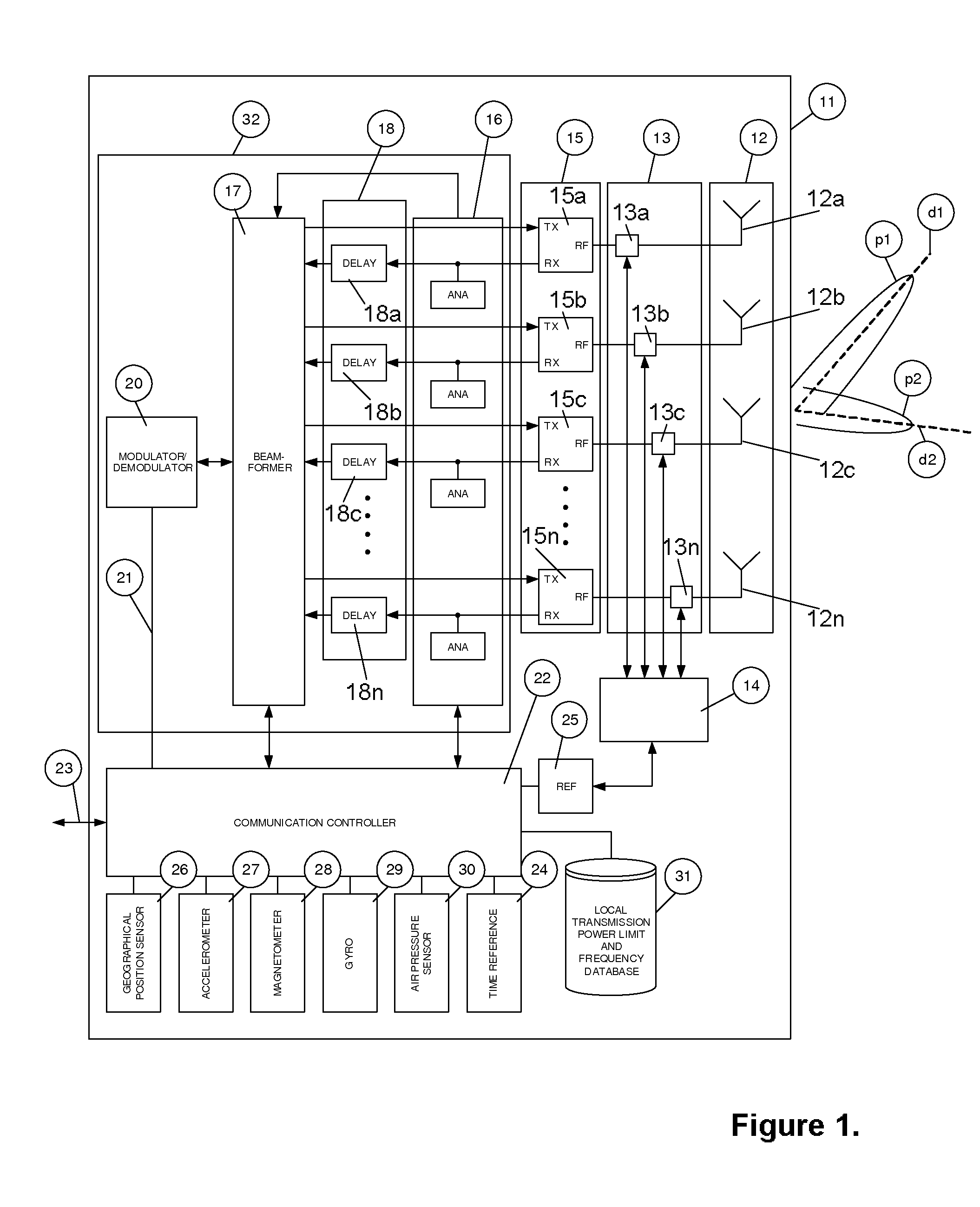
[0082]Reference is now made to FIG. 1 which is a block diagram of an embodiment of the disclosed system, implemented as a LAMBACOM unit 11. The Figure illustrates internal modules of an embodiment of the LAMBACOM unit 11 for arrangement to a communication unit. The LAMBACOM unit 11 includes as main elements an array antenna section 12, a positioning system 32, a communication controller 22, a database 31 and a data link 23 to other equipment utilizing positioning data and communication data stream to other communication units.

[0083]The array antenna section 12 includes a plurality of integrated antenna elements 12a-n which are connected to a switching section 13 including a plurality of switching units 13a-n which select whether an integrated calibration network 14 is to be connected to a plurality of RF transceiver units 15a-n of a transceiver section 15.

[0084]It should be mentioned that the calibration network 14 can be excluded in another embodiment of the LAMBACOM unit 11, and t...


PUM


Abstract

Method and system for provided a long range, high capacity ad-hoc mobile communication network where a narrow antenna beam formed by a plurality of antenna elements, radio transceivers and digital spatial signal processing is used to provide a high accuracy positioning system integrated into the communication system. The relative positions and directive orientation of all the units in the network is done by mutual exchange of positioning data as an element in the communication protocol in the network.

Description

CROSS-REFERENCE TO RELATED APPLICATION[0001]This application is a U.S. National Stage Entry from International Patent Application No. PCT / NO2012 / 050090 filed on May 16, 2012, which claims priority to Norwegian Patent Application No. 20110728 filed on May 16, 2011.BACKGROUND[0002](1) Field of Invention[0003]The disclosure relates to a system and method in the field of mobile communication.[0004](2) Description of Related Art[0005]The disclosure relates to a method of setting up a wireless long range communication network between several units communication units. Also disclosed is a system for setting up a wireless long range communication network with integrated positioning.[0006]The dominating wireless system deployments today are telecom systems optimized for RF bandwidth efficiency and low manufacturing costs for the user terminals. Examples of such systems are conventional digital GSM telecommunication systems and 3G, HSDPA, WiMAX, LTE and other 4G systems for mass distribution ...

Claims


Application Information

Patent Timeline
Patent Type & Authority Patents(United States)
IPC IPC(8): G01R31/08H04W16/28H01Q3/26H04W24/08H04W64/00H04W84/18G01S5/00G01S5/12G06F11/00G01S7/28H04B7/06G01S7/00
CPCH04W16/28G01S5/0072G01S5/12H01Q3/2605H01Q3/267H04W24/08H04W64/00H04W84/18G01S7/006G01S7/2813H04B7/0617
Inventor S.AE BUTTED.GROV, ATLEKAMBEN, ROGER
Owner RADIONOR COMM
Why Eureka
Try Eureka