
Chilled beam pump module, system, and method

a technology of pump module and chiller beam, which is applied in the direction of lighting and heating apparatus, heating types, instruments, etc., can solve the problems of not having air connections, not delivering nor inducing airflow, and large amount of costly

Active Publication Date: 2017-04-18
SEMCO INC
View PDF43 Cites 12 Cited by
  • Summary
  • Abstract
  • Description
  • Claims
  • Application Information

AI Technical Summary

Benefits of technology

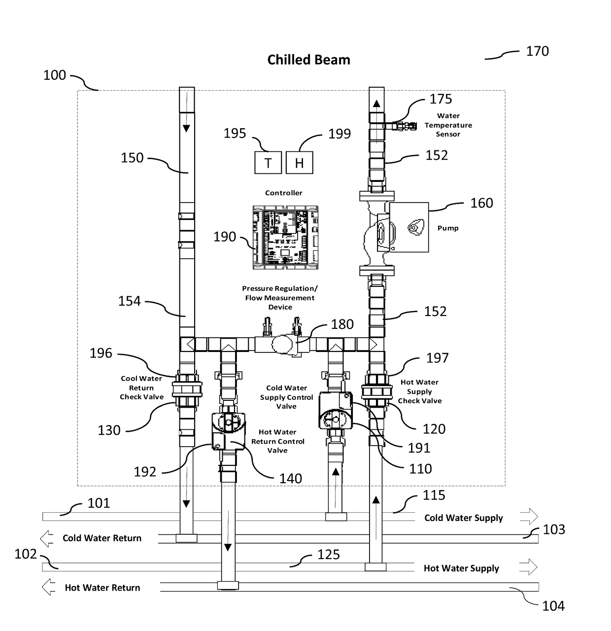
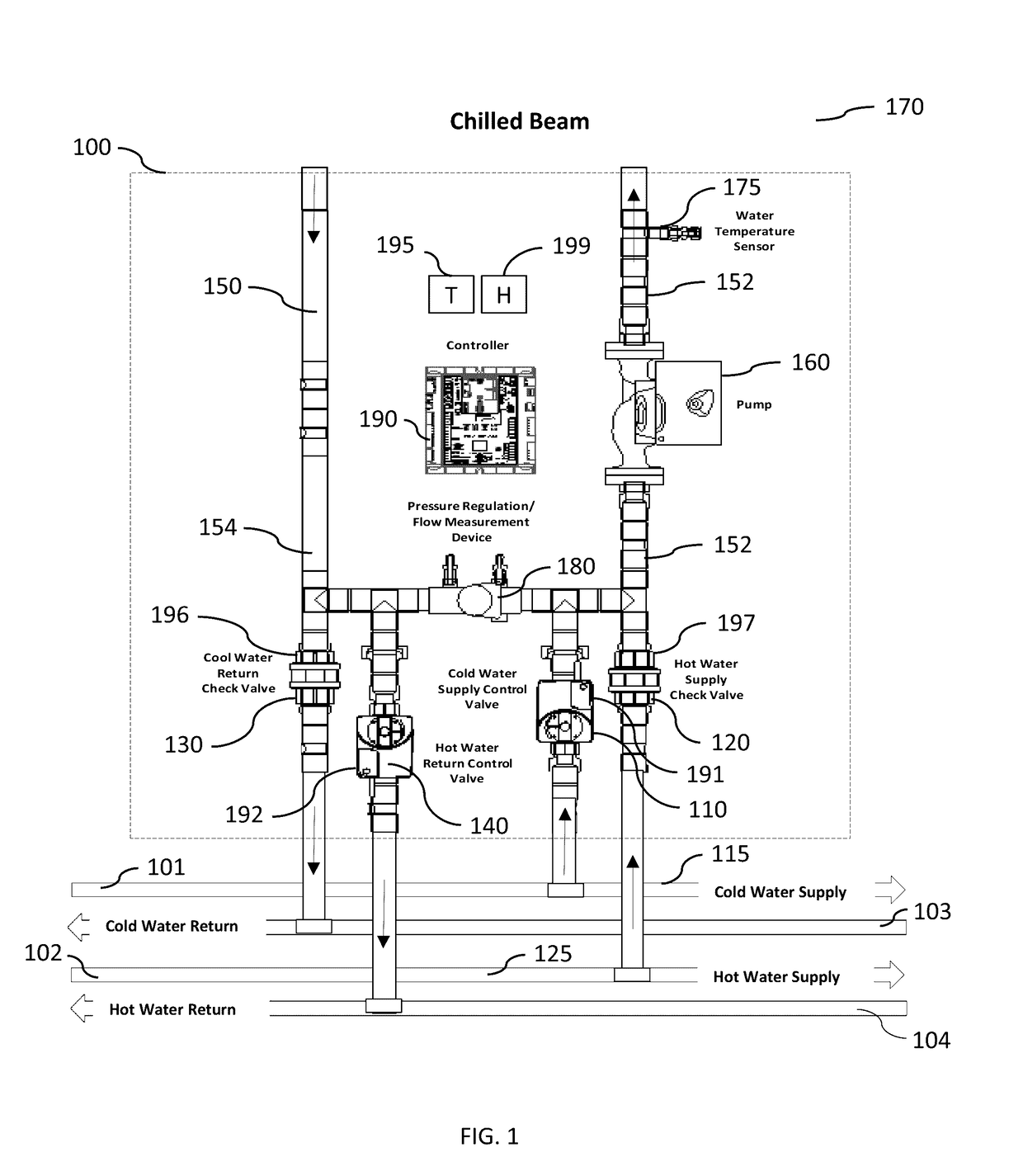
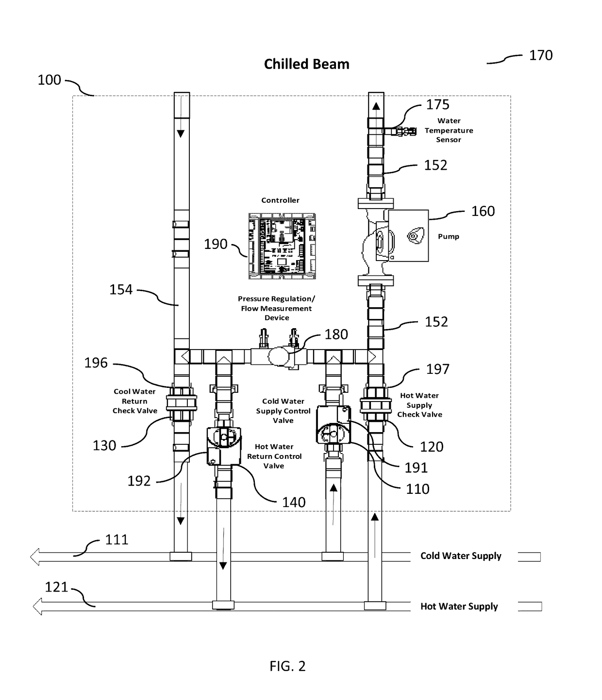
[0040]Certain embodiments provide, for example, as objects or benefits, for instance, that they improve the performance of active or passive chilled-beam system designs. Different embodiments simplify the design and installation of chilled-beam systems, reduce the installed cost of the technology, increase energy efficiency, or a combination thereof, as examples. A number of embodiments allow a conventional chilled or hot water system to be used for the primary cooling and heating water loops serving a beam network by mixing only the quantity of loop water needed with additional beam bypass water to deliver a moderate water temperature to the chilled beams so they will function properly. In certain embodiments, this solves one of the major barriers to market acceptance, namely, the requirement for two separate water loops, one for the beams and a second colder / hotter loop for the primary air handling unit serving the beams.
[0041]Further, in a number of embodiments, by allowing much-colder loop water for beam cooling and hotter loop water for beam heating, the main loop pipe size can be reduced, substantially cutting the installation cost and potentially offsetting added costs. In particular embodiments, a one-pipe design is used for heating and cooling (one pipe for each), in which case the length of the main distribution water piping can be cut in half. This addresses another major barrier to market acceptance, in certain embodiments, namely, the high cost of the distribution piping. Further, in various embodiments, all passes of the coil in the chilled beam are used for either cooling or heating, thereby increasing the output capacity when compared to more conventional designs which allocate some passes to heating and others to cooling. This allows for shorter or fewer beams to be used in many cases. Moreover, in certain embodiments, an active condensation control system continues to provide cooling to the zone while simultaneously preventing condensation on the beam surface, yet another major barrier to acceptance of the technology.
[0042]Moreover, various embodiments provide a significant increase in the temperature differential between the supply water and the return water to the chiller, enhancing chiller efficiency. Further, various embodiments provide local control of the water flow to the chilled beams and allow the option for variable flow control, which can reduce energy consumption while providing many system performance enhancements, for example, active condensation control, heating and cooling capacity boost, and improved capacity modulation, especially during times where the beam primary airflow is reduced (e.g., VAV or unoccupied periods). Furthermore, a number of embodiments greatly simplify the effort required and increase the effectiveness of the water flow balancing process within individual zones, provide greater flexibility to compensate for errors in initial load calculations or future cooling or heating capacity requirements in an individual zone, or both. Finally, particular embodiments allows for effective communication between the DOAS / primary air handling system serving the chilled beams and the individual zones. The individual zone temperature, relative humidity level, dew point, beam water temperature and other information, in a number of embodiments, may allow both the beam system and the DOAS to be improved or optimized for energy efficiency, VAV operation, condensation control, or a combination thereof, as examples.
[0051]Further, other specific embodiments of the invention provide various methods, for example, of controlling at least one chilled beam in a zone of a multi-zone air conditioning system, for instance, to reduce energy consumption, increase capacity, or both. In a number of such embodiments, the at least one chilled beam is cooled with chilled water. Such a method can include, for example, at least the acts of operating a zone pump, measuring space temperature within the zone, measuring humidity or dew point within the zone, measuring temperature of water entering the at least one chilled beam, and automatically modulating at least one chilled-water control valve. The act of operating the zone pump can include, in a number of embodiments, operating a zone pump serving the zone that both recirculates water through the at least one chilled beam and circulates chilled water from a chilled-water distribution system into the at least one chilled beam. Further, the act of automatically modulating at least one chilled-water control valve can include regulating how much water passing through the zone pump is recirculated through the at least one chilled beam and how much of the water passing through the zone pump is circulated from the chilled water distribution system. Even further, the act of automatically modulating the at least one chilled-water control valve can include maintaining the temperature of the water entering the at least one chilled beam at least a predetermined temperature differential above the dew point within the zone.

Problems solved by technology

Passive beams, on the other hand, do not have air connections, and thereby do not deliver nor induce airflow.
A common feature of typical active and passive chilled beams that both cool and heat is that they require chilled or hot water to be passed through the device to function, involve a significant amount of costly chilled and hot water piping, require careful control over the chilled water temperature, and air flow serving the beams and the space served by the beams must be effectively dehumidified to avoid condensation.
Typical heating loop water temperatures (say 140 degrees F.) should not be provided to the beams when in heating mode, in many applications, since the low velocity air leaving the beams can result in stratification which compromises both comfort of the occupants and the heating efficiency of the coils in the heating beams.
While effective, there are a number of limitations and problems with the current state-of-the-art chilled-beam system design.
Some of these limitations are considered major barriers by many engineering design firms, causing them to continue the use less energy efficient conventional HVAC systems.
This duplication of water loops and associated cost has proven to be a significant barrier to acceptance and use of chilled-beam technology.
Second, in many applications, the greatest incremental cost of a chilled-beam system is the material and installation cost associated with the water piping.
Since the current state-of-the-art chilled-beam system design involves both a supply and return piping network throughout the building for each of the hot and cold water lines, and these four runs of distribution piping commonly are copper, the cost is considerable.
Adding to the problem of high cost associated with the current approach, the size / diameter of the pipe must be relatively large to accommodate the high water flows associated with the moderate chilled and hot water temperatures required by the beams.
This high cost of chilled and hot water piping has proven to be a barrier to acceptance and use of chilled-beam technology.
Further, the use of a single pump to provide water to all zones can be both limiting and problematic.
Another common problem is that the installation of the piping and valves, due to jobsite limitations, is often less than ideal (e.g., more bends and turns than the original design) which adds pressure loss to the system which must be overcome by the main pump.
The main pump may not have the capacity to increase the pressure through the entire system to accommodate the peak load in a problematic zone or zones that need additional cooling.
Another challenge is that much of the pressure loss within the main chilled beam distribution piping can occur between the main supply water distribution pipe and the main return water pipe.
In many cases, the pipe connecting the beams to the main water lines is done in flexible PEX type tubing using special connectors that reduce installation labor but often increase the pressure loss through the system.
Yet another limitation is that the water flow to each zone has to be measured and balanced so that the chilled beams get the design flow of water in both the heating and cooling modes.
In cases where the system efficiency could benefit from a variation, however, either up or down, of the water flow to the beams, for either efficiency reasons or capacity boost, this can not be accomplished with the prior art design approach.
This concern regarding how to increase the heating or cooling capacity at the zone at the end of the piping system has proven to be a barrier to acceptance and use of chilled-beam technology.
Fourth, perhaps the most significant barrier to acceptance of the chilled-beam technology in moderately or severely hot and humid climates, commonplace in the US and Asia, is the concern for condensation on the beams.
While there are many advantages to operating chilled beams as sensible-only devices, should condensation occur, allowing water to drip directly into the occupied space, it would be a very serious problem in most applications and is typically unacceptable.
Design errors can occur, however.
In all these cases, condensation could occur.
While, when working properly, this approach can provide a level of protection against dripping water from the beams into the occupied space, it immediately cuts all cooling provided by the chilled beams to the occupied space, which is often not acceptable to the users of the space nor considered an acceptable solution by many design engineers.
This concern regarding condensation on the beams and how to avoid eliminating cooling in response to a condensation signal has proven to be a barrier to acceptance and use of chilled-beam technology.
There are few viable options to make up for this loss of performance.
The primary airflow can be increased to provide more cooling associated with the air delivered to the room, but this is a costly solution since it involves both fan energy and more conditioning at the DOAS.
Lowering the water temperature would provide added cooling output, but doing so increases the risk of condensation at the beams and, with the state-of-the-art design, means that this lower water temperature is provided to all zones.
The colder water temperature to the beams would require drier air from the DOAS which also increases energy consumption.
Increasing the beam length is the best option with regard to energy efficiency, but the cost of each beam would be increased by 15% to 25% and there is a practical limit to how much ceiling area can be allocated for the beams since light fixtures typically must also be effectively accommodated.
In addition to the higher cost associated with increasing the length of the beam, there is also a significant cost associated with changing the coil to allow for both heating and cooling.
As a result, very little flexibility is provided to accommodate varying load conditions.
For example, should a room experience a heat gain that is greater than design due to increased occupancy, higher than anticipated solar load or degradation to the chilled or hot water temperature, there is no way for the system to respond.
Once opened, the maximum cooling or heating capacity is recognized and there is no way to deliver more.
While this addresses the lower cooling requirement, it does so in a way that does not efficiently use pump energy and there can be more frequent than desired swings in room temperature.
There have also been complaints of nuisance noise associated with the control valves turning on and off associated with the initial in-rush of high pressure water.
Since chilled beams are otherwise a very quite technology, this noise is easily detected and is not easily remedied.
This can be problematic, however, if the control system uses a night setback temperature that requires a rapid morning warm up mode (i.e., higher heating output on a temporary basis).
A similar problem exists during unusually cold days when the envelope heat losses from the building are greater than design.
Likewise, since the building is unoccupied, the amount of heat normally generated by the lights and people is removed from the space, so only a small fraction of the peak cooling output from the beams is required.
While the potential energy savings are significant, the VAV enhancement presents serious challenges to the current chilled-beam system design approach.
As mentioned, if the airflow reduction is too low to handle the space latent load, the space dew point may climb causing condensation on the beams.
As a result, the rooms could remain without cooling for extended periods making it difficult to cool them back down in a timely manner, for example, the next morning.
At times like this, there may not be adequate cooling capacity delivered by the beams.
If the room gets too hot, there is no way for the prior art design to respond.
Although chilled water flow is reduced, the temperature differential (delta T) across the secondary heat exchanger or chiller remains low (e.g., only about 7 degrees) which impacts negatively on chiller performance.
Nor does it allow for optimization of the overall system.

Method used


Image

  • Chilled beam pump module, system, and method
  • Chilled beam pump module, system, and method
  • Chilled beam pump module, system, and method

Examples


Embodiment Construction

OF EMBODIMENTS

[0039]This invention provides, among other things, various controllable chilled-beam zone pump modules for controlling at least one zone of a chilled-beam heating and air conditioning system; certain multiple-zone chilled beam air conditioning systems for cooling a multiple-zone space; and particular methods of controlling at least one chilled beam in a zone of a multi-zone air conditioning system, for example, to reduce energy consumption, increase capacity, or both. Various embodiments provide, for example, as an object or benefit, that they partially or fully address or satisfy one or more of the needs, potential areas for benefit, or opportunities for improvement described herein, or known in the art, as examples.

[0040]Certain embodiments provide, for example, as objects or benefits, for instance, that they improve the performance of active or passive chilled-beam system designs. Different embodiments simplify the design and installation of chilled-beam systems, re...


PUM


Abstract

Chilled-beam zone pump modules for controlling zones of a chilled-beam heating and air conditioning system, multiple-zone chilled beam air conditioning systems for cooling multiple-zone spaces, and methods of controlling chilled beams in multi-zone air conditioning systems. Embodiments include a pump serving each zone that both recirculates water within the module and chilled beam and circulates water in and out of a chilled or warm water distribution system through valves to control the temperature of the water delivered to the chilled beams. Different embodiments provide heating as well as cooling, use check valves to reduce the number of control valves required, adjust the temperature of the beam to avoid condensation, change pump speed to save energy or increase capacity, can be used in two- or four-pipe systems, or a combination thereof.

Description

RELATED PATENT APPLICATIONS[0001]This patent application claims priority to Provisional Patent Application No. 61 / 594,231, filed on Feb. 2, 2012, titled CHILLED BEAM PUMP MODULE, SYSTEM, AND METHODS, having at least one inventor in common and the same assignee. In addition, the contents of this priority patent application are incorporated herein by reference. Certain terms, however, may be used differently.FIELD THE INVENTION[0002]This invention relates to chilled beam heating, ventilating, and air conditioning (HVAC) systems and components and equipment for such systems and to methods of configuring and controlling chilled beam HVAC systems. Particular embodiments relate to multi-zone chilled-beam systems. Some embodiments both cool and heat.BACKGROUND OF THE INVENTION[0003]Active chilled beams provide an energy-efficient way to provide sensible cooling to a space. High energy efficiency can be achieved by accomplishing most of the space sensible cooling utilizing moderate temperat...

Claims


Application Information

Patent Timeline
Patent Type & Authority Patents(United States)
IPC IPC(8): G05D23/00F28F27/00F24F5/00
CPCF28F27/00F24F5/0003F24F5/0089F24F5/0092F24D3/02F24F5/00F24F3/08
Inventor FISCHER, JOHN C.MESCHER, KIRK T.MITCHELL, RICHARD K.GLEN, STEPHEN P.CARROLL, STEVEN S.
Owner SEMCO INC
Learn More