
Method and apparatus for altering material

a technology of material and applied in the field of methods and apparatus for altering materials, can solve the problems of unsatisfactory expectations of such technologies, limited commercial success of laser thermally altering the near surface characteristics of materials, and inconvenient treatment, etc., to achieve high average power and repetitive operation, high energy, and low cost

Inactive Publication Date: 2002-02-05
SANDIA
View PDF7 Cites 2 Cited by
  • Summary
  • Abstract
  • Description
  • Claims
  • Application Information

AI Technical Summary

Benefits of technology

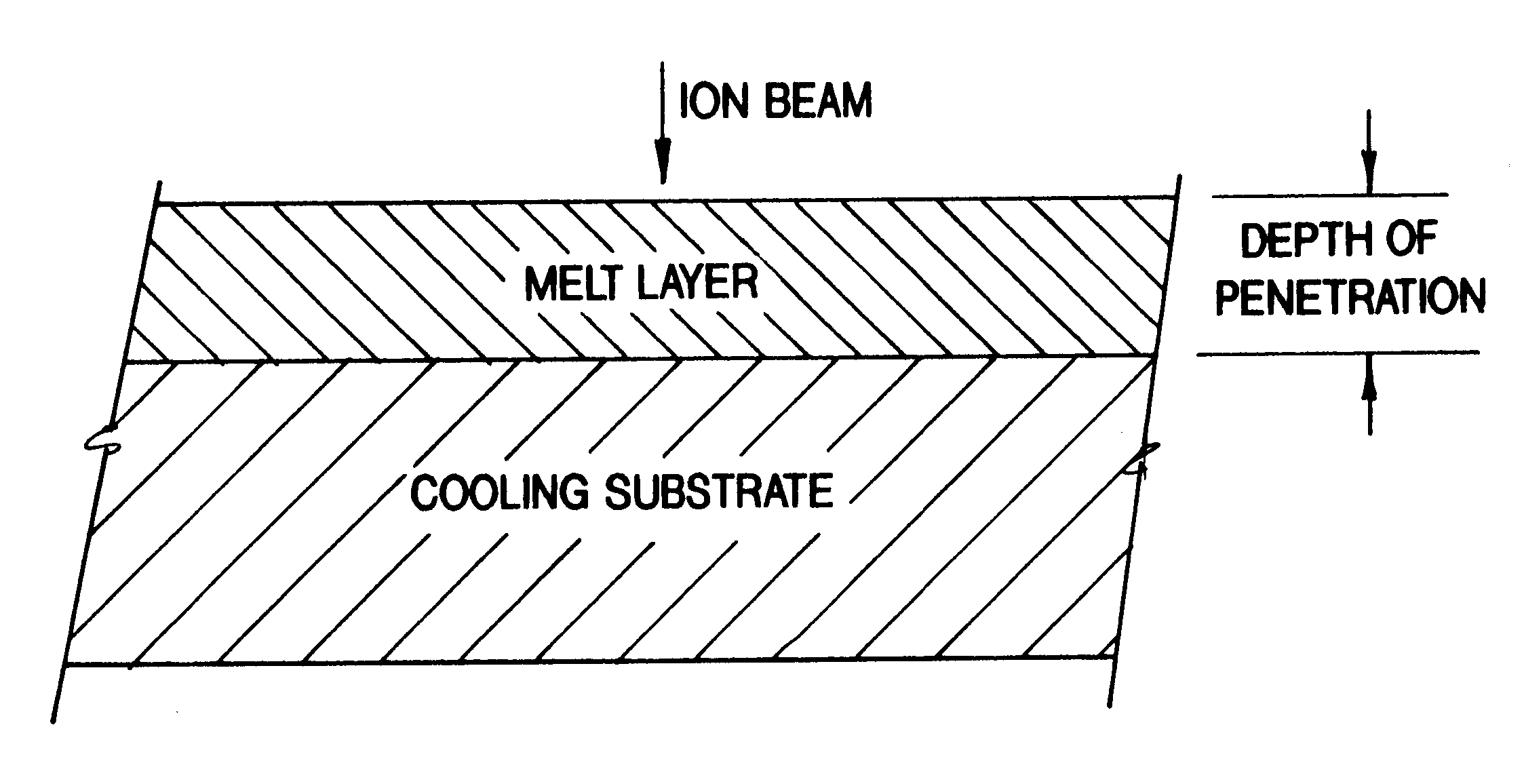
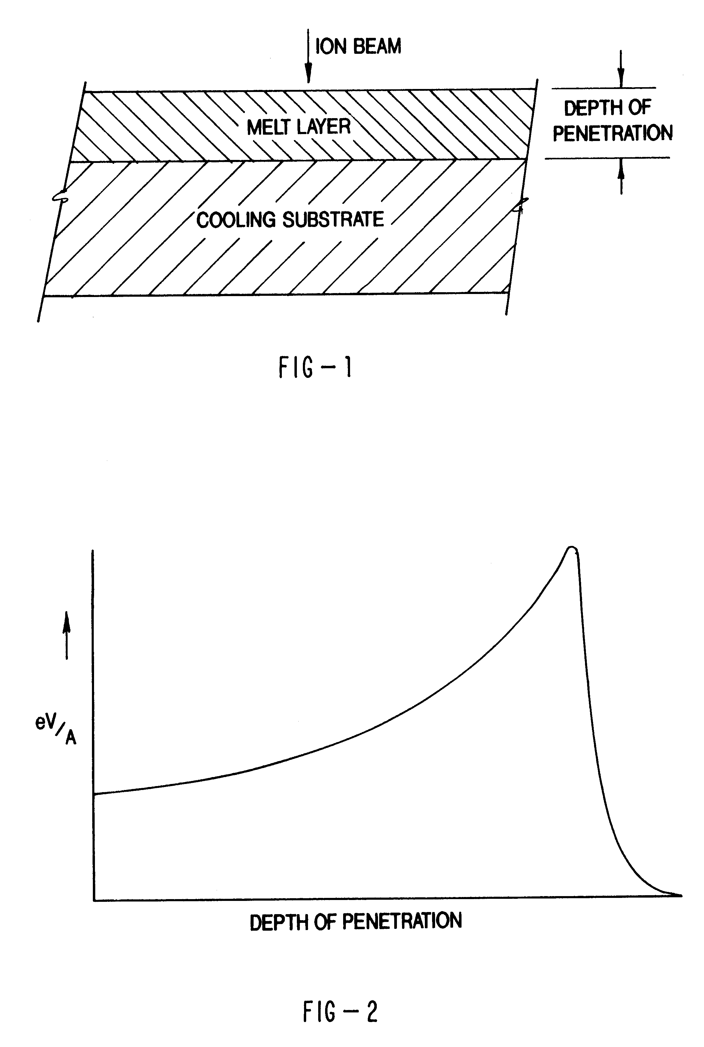
The present invention provides a system for generating a high energy, ion beam repetitively over an extended number of operating cycles. In particular, the present invention provides an ion beam generator capable of high average power and repetitive operation over an extended operating cycle for thermally treating large surface areas of a material at low cost. The ion beam generator comprises a high energy, pulsed power system and an ion beam source both capable of high repetition rates, and both have an extended operating life. High energy, repetitively pulsed ion beams produced according to the present invention can produce surface treatments ranging from localized high temperature anneals to melting, both followed by rapid thermal quenching to ambient temperatures. In metals this can produce complex surface alloys, liquid phase mixing of layers of different materials, and / or non-equilibrium microstructures including amorphous, disordered crystalline, and nanocrystalline phases. Other applications include etching and cross-linking of polymers, surface glazing and sealing of ceramic surfaces and cost-effective dry processes for surface deburring, polishing, and cleaning without the use of solvents. The unique energy deposition in-depth characteristic of high energy, repetitively pulsed ion beams also allows this technology to be used as a new technique for bonding of films to substrates. The depth of treatment can be controllable by varying the ion energy and species as well as pulse duration or length.

Problems solved by technology

Unfortunately, the dramatic expectations of such technologies have largely gone unfulfilled.
In particular, the use of lasers for thermally altering the near surface characteristics of materials has met with only limited commercial success.
The more significant reasons for such poor reception are: 1) high cost per area treated, 2) short (<50 nm) deposition depths in metals, 3) high reflectivity of metal surfaces, 4) large variations in photon absorption leading to non uniform treatment due to defects and non-uniformities in treated surfaces, and 5) low power levels require the use of small (typically .ltoreq.1 cm.sup.2) beam spots which must then be swept across a surface to treat large areas which can lead to undesirable mechanical and electrical edge effects in surfaces treated with swept beams.
The use of ion beams for thermally altering the near surface characteristics of a material, while the most promising, has been fraught with the most substantial problems.
Most notable of the limitations with existing ion beam technologies have been: 1) high costs per area treated, 2) the inability to generate a large number of pulses without the costly replacement of ion beam generator components, 4) low repetition rates, 5) low average power, and 6) the inability to reliably produce a uniform ion beam of a single selectable ion species.
Other difficulties arising from flashover include: the production of large quantities of neutral gas that makes high repetition rate difficult, generated debris can contaminate surfaces being treated, and non uniformity and irreproducibility of the beam in some cases due to the localized and difficult to control nature of flashover.
Second, the inability of the ion beam generator to operate repetitively for an extended number of operating cycles (>>10.sup.3) without replacement of major components.
Third, the inability to operate with electrical efficiencies >5%.
These limitations alone have made it impossible to consider industrial applications of the ion beam technology for surface treating materials.

Method used


Image

  • Method and apparatus for altering material
  • Method and apparatus for altering material
  • Method and apparatus for altering material

Examples


examples

Applications of present invention include production of low cost materials with treated surfaces for handling corrosive environments and treatment of large area metal sheets and critical components used in manufacturing and other areas where hardness, toughness and corrosion or wear resistance are important. It can also be used to produce smooth, crack-resistant ceramic surfaces by melting and re solidification using pulsed ion beams. By varying ion beam deposition levels and pulse durations it is also possible to use this technology for either surface cleaning or annealing. At high deposition levels (.about.30 J / cm.sup.2) it is possible to do shock hardening of materials. Polymer processing and ion implantation can be done at lower deposition levels.

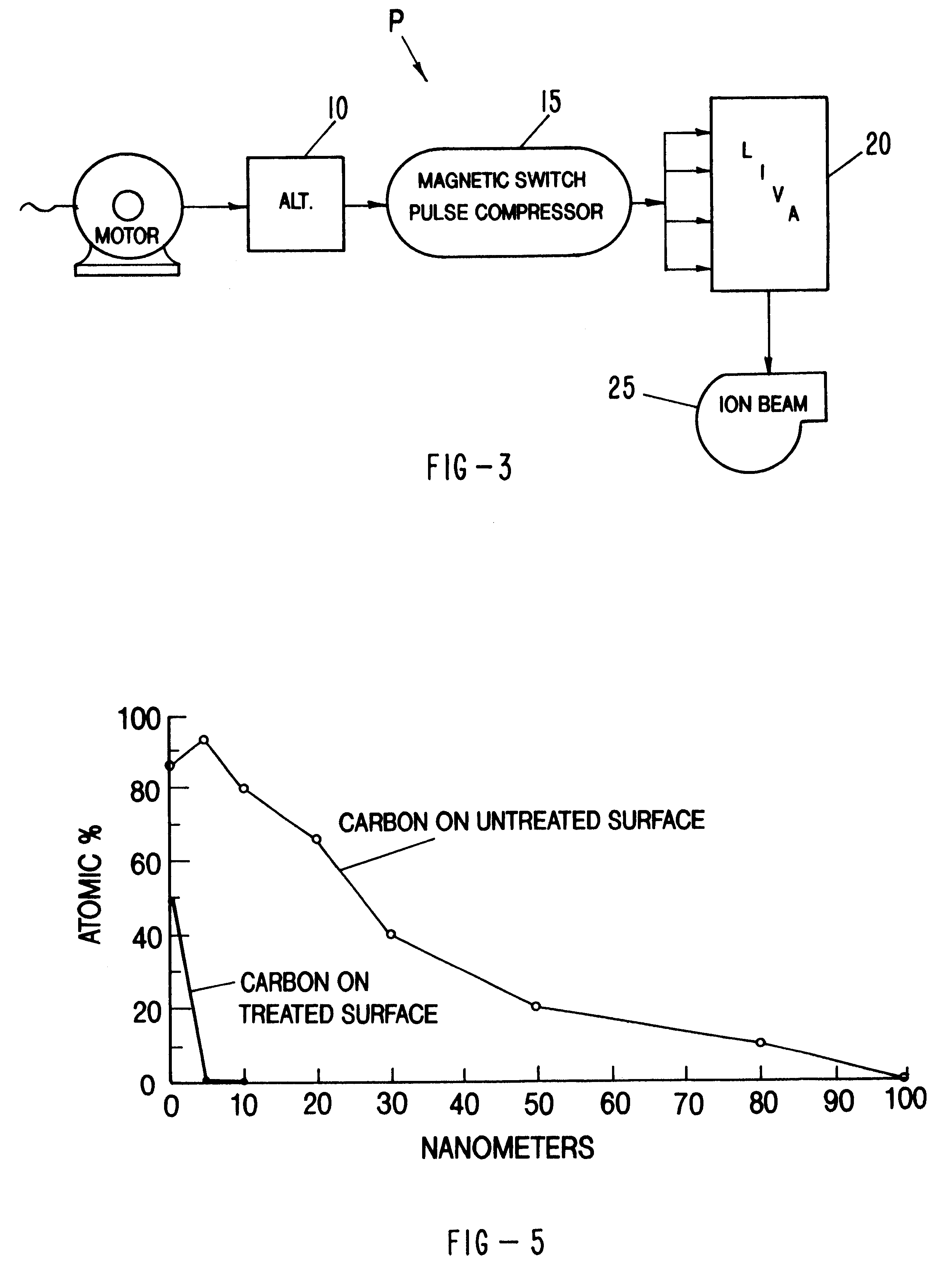
Examples of thermal surface treatment using this process are shown in FIGS. 5, 6, 7a, 7b and 8a, 8b. Surface cleaning or preparation without the use of organic solvents, can be accomplished by choosing higher mass ions (e.g. nitrogen, c...


PUM

PropertyMeasurementUnit
impedanceaaaaaaaaaa
impedanceaaaaaaaaaa
voltageaaaaaaaaaa

Abstract

Methods and apparatus for thermally altering the near surface characteristics of a material are described. In particular, a repetitively pulsed ion beam system comprising a high energy pulsed power source and an ion beam generator are described which are capable of producing single species high voltage ion beams (0.25-2.5 MeV) at 1-1000 kW average power and over extended operating cycles (108). Irradiating materials with such high energy, repetitively pulsed ion beams can yield surface treatments including localized high temperature anneals to melting, both followed by rapid thermal quenching to ambient temperatures to achieve both novel and heretofore commercially unachievable physical characteristics in a near surface layer of material.

Description

BACKGROUND OF THE INVENTIONThe present invention relates generally to methods and apparatus for altering material. More particularly, the present invention describes methods and apparatus for thermally altering the near surface characteristics of a material with a high energy, repetitively pulsed ion beam.A variety of techniques have been developed for thermally altering the near surface characteristics of a material using ion beam, electron beam, x-ray and laser technologies. Unfortunately, the dramatic expectations of such technologies have largely gone unfulfilled. In particular, the use of lasers for thermally altering the near surface characteristics of materials has met with only limited commercial success. The more significant reasons for such poor reception are: 1) high cost per area treated, 2) short (<50 nm) deposition depths in metals, 3) high reflectivity of metal surfaces, 4) large variations in photon absorption leading to non uniform treatment due to defects and no...

Claims


Application Information

Patent Timeline
Patent Type & Authority Patents(United States)
IPC IPC(8): B29C59/16B29C59/00C23C14/48C23C8/36C23C8/06H01J27/14H01J27/02B29C35/08G21K5/04H01J3/04H01J27/00H01J27/08H01J37/08H01L21/48
CPCB29C59/16B29C2035/0872C08J7/123C23C8/36C23C14/48H01J27/14H01J2237/08H01J2237/31701
Inventor STINNETT, REGAN W.GREENLY, JOHN B.
Owner SANDIA
Learn More