
Vertical external cavity face emitting semiconductor laser with concave-convex mirror

A reflective mirror and semiconductor technology, applied in the direction of semiconductor lasers, lasers, laser components, etc., can solve the problems of reducing device efficiency and output power, increasing device lasing threshold, etc., to improve output power, facilitate beam coupling, and good resistance Effects of laser damage

Inactive Publication Date: 2008-04-23
CHANGCHUN INST OF OPTICS FINE MECHANICS & PHYSICS CHINESE ACAD OF SCI
View PDF4 Cites 0 Cited by
  • Summary
  • Abstract
  • Description
  • Claims
  • Application Information

AI Technical Summary

Problems solved by technology

However, due to the use of this plano-concave mirror, it has a scattering effect on the light traveling in the formed optical resonant cavity, which will inevitably increase the lasing threshold of the device and reduce the efficiency and output power of the device.

Method used


Image

  • Vertical external cavity face emitting semiconductor laser with concave-convex mirror
  • Vertical external cavity face emitting semiconductor laser with concave-convex mirror
  • Vertical external cavity face emitting semiconductor laser with concave-convex mirror

Examples


Embodiment 1

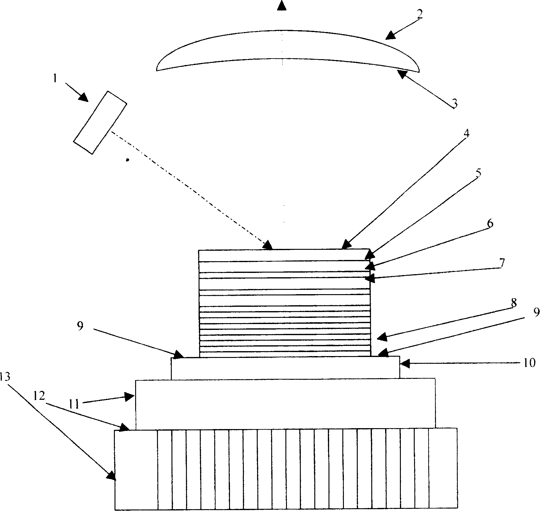
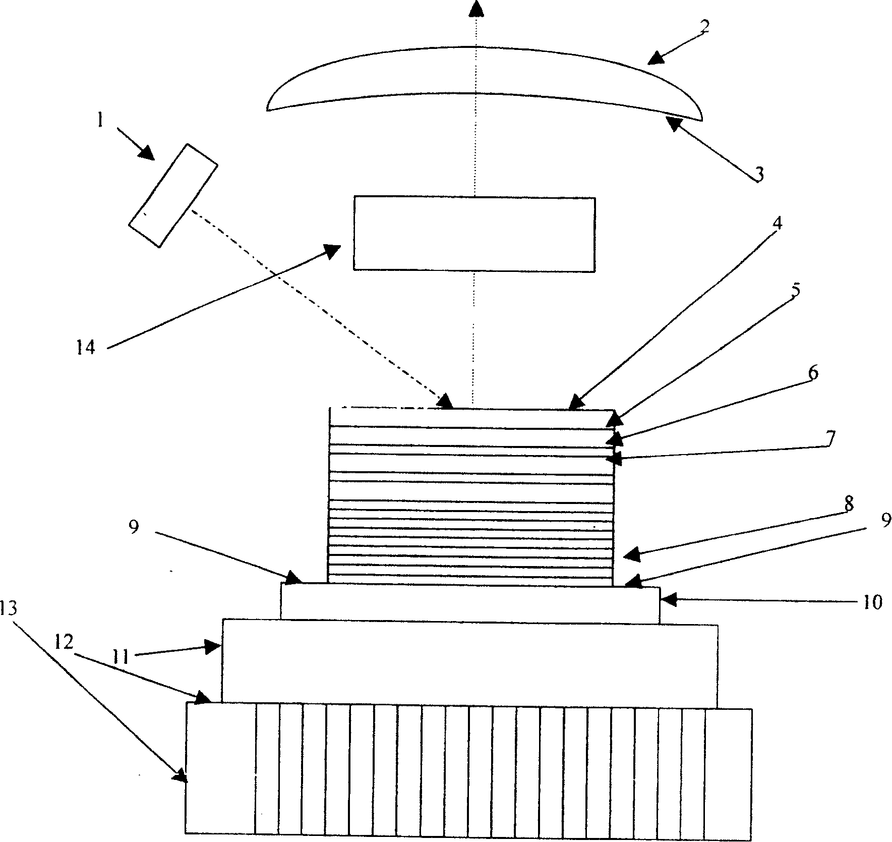
[0011] The pump light source 1 is a high-power 800-810nm wavelength semiconductor laser array, the convex-convex mirror 2 is made of k9 optical glass or quartz, the concave surface curvature half-diameter is 5 mm or 25 mm, and the convex surface curvature radius is 5 mm or 9.5 mm , the highly reflective dielectric film 3 adopts Si / SiO2 dielectric film, and the reflectivity is 95%-99%. The anti-reflection coating 4 is made of HfO2 material, and the effective refractive index selected by the anti-reflection coating is n eff = n 0 n 1 , The effective refractive index of HfO2 material selection is 1.85-1.90. The window layer 5 is made of GaIn0.49P material. The light absorbing layer 6 is made of Al0.06GaAs material. The active gain region 7 can be a periodic active multi-quantum well gain region, and its diameter can be from 5...

Embodiment 2

[0013] Embodiment 2: pumping light source 1, reflective medium film 3, anti-reflection film 4 and window layer 5, solder 9, heat sink 10, heat sink 11, thermal conductive adhesive 12 and microchannel heat sink 13 are the same as in embodiment 1, with convex and concave The semi-diameter of curvature of the concave surface of the reflecting mirror 2 is 50 mm, and the radius of curvature of the convex surface is 25 mm. The light absorbing layer 6 is Al0.2GaAs, the periodic multi-quantum well active gain region 7 is GaAs quantum wells and Al0.2GaAs potential barriers, and the Bragg reflector 8 is made of 30 pairs of AlAs / Al0.2GaAs materials. The present invention is the same as Embodiment 1 in terms of process.

Embodiment 3

[0014] Embodiment 3: frequency doubling in the cavity of a 980nm vertical external cavity surface-emitting semiconductor laser with a convex-concave mirror, the nonlinear crystal 14 is an LBO crystal, the concave curvature of the convex-concave mirror 2 is selected to be 100 mm, and the convex curvature radius can be selected to be 50 mm . Other components are the same as in Embodiment 1.


PUM


Abstract

This invention relates to a structure design of a vertical outer cavity emit semiconductor laser including a pump light source, a concave-convex reflection mirror, a reflection medium membrane, an anti-reflection film, a window layer, a light absorption layer, an active gain zone, a Bragg reflection mirror, a soldering material, a radiating fin, a heat sink, a heat conduction glue, a micro-channel radiation fin and a non-linear crystal, which utilizes the convex face convergence of a concave-convex reflection mirror to reduce light diffusion and increase light feedback to reduce the lasing threshold of the device to increase its output power.

Description

Technical field: [0001] The invention belongs to the field of semiconductor lasers and relates to the structural design of vertical external cavity surface emitting semiconductor lasers. Background technique: [0002] Vertical-cavity surface-emitting semiconductor lasers are one of the most active research topics in the field of optoelectronics. Compared with edge-emitting semiconductor lasers, vertical-cavity surface-emitting laser devices have a smaller far-field divergence angle, a circular spot, and are easy to excite in a single longitudinal mode. It has a wide range of application prospects in optical communication, optical interconnection, and optical integration, and has aroused great interest. Vertical external-cavity surface-emitting semiconductor lasers are emerging representatives of vertical-cavity surface-emitting semiconductor lasers. With their high output optical power, good beam quality and easy two-dimensional array, they are widely used in laser display, ...

Claims


Application Information

Patent Timeline
Patent Type & Authority Patents(China)
IPC IPC(8): H01S5/00
Inventor 晏长岭秦丽何春凤单肖楠路国光
Owner CHANGCHUN INST OF OPTICS FINE MECHANICS & PHYSICS CHINESE ACAD OF SCI
Learn More