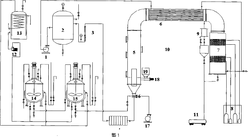
[0033] The invention provides a process and equipment for manufacturing polymer-coated controlled-release fertilizer. The spray precipitation phase inversion method coating process flow chart shown in Figure 1. The process combines the fluidized bed spray pyrolysis method with the solvent evaporation precipitation phase conversion method, and establishes a spray precipitation phase conversion method based on the spray fluidized bed preparation of fertilizer controlled release film. This method first makes the material particles in a stable circulating fluidized state, and then uses a two-fluid nozzle to spray the film-making liquid such as organic polymer on the surface of the moving particles, and hot air is used to promote the film-making liquid that settles on the surface of the particles. The solvent and the solute are separated into phases, the solvent changes from a liquid phase to a gas phase to volatilize, and the solute changes from a highly dispersed liquid phase to a solid phase with a permeable membrane structure.
[0034] Based on the above process operation requirements, the spray fluidized bed equipment involved in the present invention consists of Roots blower, gas buffer tank, electric heater, fluidized bed, tubular condenser, air cooler, air compressor, heating constant temperature stirring reaction The kettle, nozzles and other equipment and control system are composed of the Roots blower 1 connected to the gas buffer tank 2, and the gas buffer tank 2 is connected to the bottom of the spouted fluidized bed 5 through the rotameter 3 and the electric heater 4; the guide tube 22 Fixed at the lower part of the spouted fluidized bed 5, the two-fluid nozzle 16 and air compressor 17 as an atomization system are fixed at the nozzle liquid phase inlet at the bottom of the spouted fluidized bed 5; the top of the spouted fluidized bed 5 is connected to the condenser 6 Inlet, the outlet of the condenser 6 is connected with the indoor unit 7 as an air cooler, and the room amplifier 8; the viewing cup 9 as a solvent collection system is connected to the connection between the outlet of the condenser 6 and the indoor unit 7, the solvent collector 10 and solvent recovery The tank 11 is connected under the sight cup 9; the heat transfer oil pump 12, the heat transfer oil storage tank 13, and the constant temperature heating and stirring reactor 14 and 15 are connected in series as the coating liquid preparation system, and then pass the control valve and spray the nozzle liquid at the bottom of the fluidized bed 5 The phase inlet is connected.
[0035] The bottom cone angle of the bottom cone 21 of the spouted fluidized bed 5 is 55°-65°. In order to facilitate observation, the first observation port 24, the second observation port 25, the third observation port 26 and the fourth observation port 27 are arranged on the bed wall of the spouted fluidized bed 5; they are arranged at a height of 160mm under the fluidized bed wall Screw feeder 18 and feeding funnel 19; a discharge port is set at the bottom.
[0036] FIG. 2 shows the specific structure of the gas buffer tank 2. The buffer tank has an air inlet 72, an air outlet 70, a vent 69, a liquid discharge port 71 at the bottom, and a pressure gauge 68 at the top. Its function is to buffer the gas sent by the Roots blower 1 to make it stable. The gas provided by the impeller type Roots blower is a pulsed airflow, which makes the fluidization state of the particles fluctuating. For this reason, a buffer tank is used to make the airflow evenly mixed here and balance the stability of the airflow. If the rated working flow of the Roots blower is 0.25m 3 /sec, the number of revolutions is 960r/sec, the residence time can be designed to be 5sec, then the buffer tank volume needs to be: 0.75m 3. Designing a tank with DN800mm and height of 1560mm can meet the requirements.
[0037] The design power of the electric heater is 15kw, 135 electric heating wires 57 with a power of 1kw are covered with a porcelain ring, and they are threaded in the horizontally distributed 270 DN32 iron pipes 56 (as shown in Figure 3). After three electric heating wires are connected in series , Parallel connection, each 15 groups is one phase, and the star connection is three-phase 60. A large number of heating wires and iron pipes can ensure that the heat exchanger has a large heat exchange area and heat exchange efficiency; the use of 1kw electric heating wires and every three wires in series can ensure the durability of the heating wires while reducing the single wire The load of the heating wire (its actual power is only 11% of the rated power), the heating wire only generates heat without redness, which can increase its service life. In addition, a thyristor three-phase voltage regulator is used to control its voltage. The actual working voltage is controlled within 120 volts (V) according to the design, which can improve the safety of equipment power consumption; at the same time, it can be accurately adjusted by automatically adjusting the voltage level. Control the temperature of the heated air and keep it constant within ±2°C of the set temperature. The two ends are the pipe inlet 58 and the outlet 59 respectively.
[0038] Figure 4 shows the design basis of the spouted fluidized bed 5: fertilizer particles with a diameter of 2-4mm are blown up at the bottom of the spouted fluidized bed 5 and fall back at the top. For this reason, the air flow rate should be greater than 30m/sec. , If the wind supply capacity is 0.25m 3 /sec design, the diameter of the gas inlet at the bottom of the spouted fluidized bed 5 is DN100mm, the diameter of the cylinder of the spouted fluidized bed 5 is DN500mm, and the height of the fluidized bed is 2000mm. The guide tube 22 is fixed at the bottom of the spouted fluidized bed 5, The cylinder 22 has a diameter of DN200mm and a height of 600m, and can be raised and lowered freely; in order to make the fertilizer particles circulate well and there is no dead corner at the bottom, the cone angle of the bottom cone 21 of the spouted fluidized bed 5 is less than 60°. In order to facilitate observation, the spouted fluidized bed 5 has a first observation port 24, a second observation port 25, a third observation port 26, and a fourth observation port 27 on the wall of the spouted fluidized bed; Feeder 18 and feeding funnel 19; the bottom is provided with a discharge port.
[0039] Figure 6 is a schematic diagram of the condenser equipment. The condenser is designed as an air-air exchange tube type, with hot air running through the tube and cooling air through the shell. According to the law of heat balance and heat transfer calculation formula, as well as the saturation concentration of the solvent in the air, determine the overall heat transfer efficiency and heat transfer area of the heat exchanger. The specific structure is that the cylinder has a diameter of DN500mm and a length of 3000mm. The two ends of the cylinder are provided with a cooling medium inlet 46 (as shown in Figure 6a) and an outlet 47 respectively. There are 100 DN20 and 3000mm long tubes 45 inside, which follow an isosceles triangle. Evenly arranged (as shown in Figure 6b, c).
[0040] The air cooling system includes an indoor unit 7, an outdoor unit 8. The indoor unit is composed of a finned serpentine evaporator and its cabinet, and the outdoor unit is a compressor unit that provides a cold source. First use a elbow exhaust tube to connect the indoor unit to the condenser, and then use a section of elbow exhaust tube to connect the indoor unit to the condenser shell side. Indoor cabinet structure: length, width and height are 1440mm, 900mm and 900mm respectively. The evaporator structure is designed with a chip spacing of 3.5mm, row depth is 5 rows, and the actual heat transfer area is F Z1S = 38.5m 2. The outdoor unit uses a two-stage compressor unit with a total cooling capacity Q 0 = 22.89kw.
[0041] The solvent collection system includes: a sight glass 9 for observing the condensed and recovered downstream solvent, and the recovered solvent is temporarily collected by the solvent collector 10, and the excessive solvent in the collector enters the solvent recovery tank 11 through the discharge port at the bottom. The middle of the viewing cup is a glass cylinder, and the two ends are connected by flanges; as shown in Figure 7a, the solvent collector is provided with a solvent inlet 61 and a vent 62 on the upper part; the collector is provided with level gauge installation ports 63, 64 in the vertical direction; The lower part is tapered, and a discharge port 65 is provided. FIG. 7b shows a schematic diagram of the feed hopper, and the feed port 67 is connected to the feed hopper 19 by a connecting flange 66 below.
[0042] The coating liquid preparation system includes: a heat-conducting oil pump 12, a heat-conducting oil storage tank 13, and thermostatic heating and stirring reactors 14 and 15. The heat-conducting oil storage tank (as shown in Figure 8) is a closed cylinder with a diameter of DN600mm and a height of 1260mm. A cooling water coil 55 is installed inside. The cylinder is equipped with a coil inlet 50 and an outlet 51, and a liquid level gauge is installed in the vertical direction. Installation ports 52 and 53; the top is provided with a right heat conduction inlet 48 and a drain port 49, and the lower side is provided with a heat conduction oil outlet 54.
[0043] The structure of the electric heating thermostatic stirring reactor is shown in Figure 9. In order to accurately control the temperature of the materials in the reactor (for example: 120℃±2℃), heat-conducting oil is used to heat the organic solvent, which is directly heated by an electric heating rod. In order to make the polymer dissolve quickly and the solution uniformly, an impeller mechanical stirring tank 44 is installed; in order to enable the coating solution to be smoothly transported to the spray head, the reactor is designed as a pressure-resistant equipment, and the tank body, flange and head are designed with pressure resistance 10MPa; an explosion-proof seal is set at the junction of the mechanical stirring and the head of the reactor. The specific nozzle settings include: the top head solvent inlet 33, polymer and other solid material inlet 34, temperature monitoring hole 37, compressed gas inlet 35, vent 36; the bottom of the kettle is provided with a coating liquid discharge port 43; the upper part of the heating jacket Set a temperature monitoring hole 38, a temperature automatic control sensor hole 39, and four electric heating rod sockets 41 at the lower part, evenly distributed, each electric heating rod power is 2kw, one is reserved for spare, the other three are connected according to the three-phase star connection mode Connected, a heat transfer oil inlet 42 is provided at the bottom of the heating jacket, and a heat transfer oil outlet 40 is provided at the top.
[0044] The atomization system includes a compressed air machine 17 and a two-fluid nozzle 16. Because one of the core points of the spray precipitation phase inversion method is to disperse the coating liquid into ultrafine particles to promote solvent volatilization speed and polymer molecular reorganization and crystallization, and the two-fluid nozzle can make the liquid atomization reach the micron level. By changing the pressure and flow of the two phases, the atomization state can be adjusted in a relatively wide range, thereby adjusting the controlled release performance of the coated fertilizer. However, the liquid phase of the traditional two-fluid nozzle is generally water, and the design of its air cap cannot be used in this process. For this reason, the present invention improves the design of an air cap of a two-fluid nozzle (as shown in Figure 5, 28 is a liquid flow adjustment bolt, 29 is a gas phase inlet, 30 is a liquid phase inlet, 31 is a liquid distribution cap, and 32 is an air distribution cap. Cap.) Shorten the outlet of the original air cap so that the mixing of air and liquid can be carried out directly in the air, which solves the problem of crystallization and blockage of the coating liquid at the outlet and ensures normal operation.