

Nano carbon pipe composite field-emission source and manufacturing method thereof
A technology of carbon nanotubes and emission sources, which is applied in the manufacture of discharge tubes/lamps, discharge tubes, cold cathodes, etc., can solve the problems of low resolution, poor uniformity of field emission, and low utilization of carbon nanotubes, and achieve The equipment and process are simple, the working voltage and energy consumption are reduced, and the effect is suitable for large-scale production
- Summary
- Abstract
- Description
- Claims
- Application Information
AI Technical Summary
Problems solved by technology
Method used
Image

Examples
Embodiment 1
[0038] In this embodiment, Fe-Al-Cr fiber woven cloth is used as the substrate, and the area of Fe-Al-Cr woven cloth is 2×2cm 2 , Fe-Al-Cr fiber diameter is 1 μm. The steps of making a carbon nanotube composite field emission source on the substrate are as follows:
[0039] (1) Preparation of carbon nanotube organic growth solution: measure 50mL p-xylene C 8 h 10 , add 20 mg of ferrocene and 2 g of silicon oxide powder with an average particle diameter of about 2 mm.
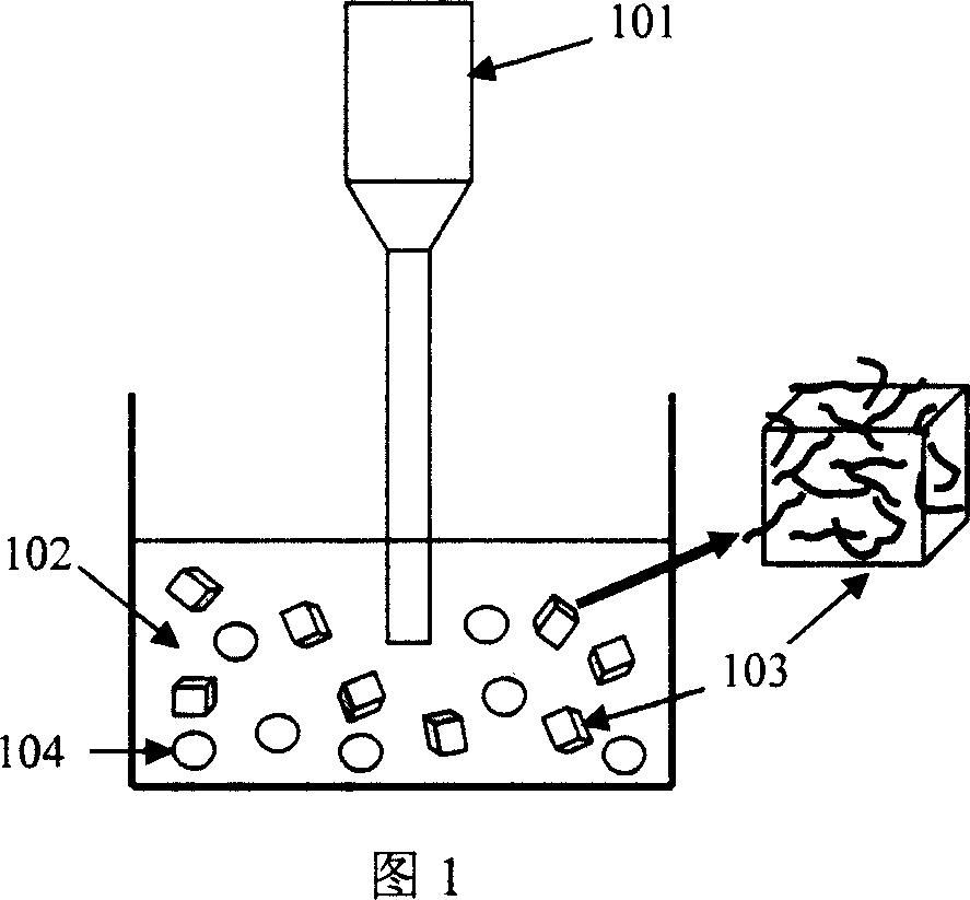
[0040] (2) Sonochemical synthesis of carbon nanotubes (see FIG. 1 ): put the beaker containing the above-mentioned organic growth solution 102 into an ice bath, then insert an ultrasonic probe 101 for ultrasonic treatment—the ultrasonic frequency is 20 kHz, and the ultrasonic power is 300 W. The ultrasonic treatment time is 20 minutes; during the ultrasonic treatment process, the organic growth liquid 102 undergoes a sonochemical reaction, and carbon nanotubes are generated on the surface of the silicon oxi...
Embodiment 2
[0044] In this embodiment, carbon fiber woven cloth is used as the substrate, and the area of carbon fiber woven cloth is 2×2cm 2 , with a carbon fiber diameter of 2 μm. The steps of making a carbon nanotube composite field emission source on the substrate are as follows:
[0045] (1) Ti film deposited by electron beam evaporation: a Ti film with a thickness of 20 nm was evaporated on the above-mentioned carbon fiber woven cloth by electron beam evaporation method to enhance the bonding force between carbon nanotubes and carbon fiber substrate.
[0046] (2) Preparation of carbon nanotube organic growth solution: Measure 50 mL of decane, add 2 mg of iron pentacarbonyl and 0.5 g of silicon oxide powder with an average particle diameter of about 3 mm.
[0047] (3) Sonochemical synthesis of carbon nanotubes (see Figure 1): Put the beaker containing the above-mentioned organic growth solution into an ice bath, and then insert an ultrasonic probe for ultrasonic treatment—ultrason...
Embodiment 3
[0051] The preparation steps are the same as in Example 2, using carbon fiber woven cloth as the substrate, and the area of the carbon fiber woven cloth is 2×2cm 2 , with a carbon fiber diameter of 3 μm. The steps of making a carbon nanotube composite field emission source on the substrate are as follows:
[0052] (1) Electron beam evaporation of Mo film: a Mo film with a thickness of 5 nm was evaporated on the above-mentioned carbon fiber woven cloth by electron beam evaporation to enhance the bonding force between the carbon nanotubes and the carbon fiber substrate.
[0053] (2) Preparation of carbon nanotube organic growth solution: Measure 50 mL of decalin, add 4 mg of nickel tetracarbonyl, 0.5 g of silicon oxide powder with an average particle diameter of about 1 mm, and 0.1 mg of thiophene.
[0054](3) Sonochemical synthesis of carbon nanotubes (see Figure 1): put the beaker containing the above-mentioned organic growth solution into an ice bath, and then insert an ul...
PUM
| Property | Measurement | Unit |
|---|---|---|
| Diameter | aaaaa | aaaaa |
| Length | aaaaa | aaaaa |
| Diameter | aaaaa | aaaaa |
Abstract
Description
Claims
Application Information