Bidirectional luminescent heat radiation LED

A light-emitting diode, two-way technology, applied in lighting and heating equipment, components of lighting devices, cooling/heating devices of lighting devices, etc., can solve problems such as color temperature change, luminous flux reduction, carbonization and blackening, and achieve color temperature without occurrence Change, working life extension, effect of life extension

Inactive Publication Date: 2008-02-13
CHANG HSIN HIGH INTENSITY LED DONG GUAN
View PDF1 Cites 14 Cited by
  • Summary
  • Abstract
  • Description
  • Claims
  • Application Information

AI Technical Summary

Problems solved by technology

[0004] 1. The utilization rate of the light emitted by the chip is low: see Figure 1-2: chip 03 or chip 4 emits light on one side, and chip 03 or chip 4 does not emit light on the side of the bowl, but can only pass through the bowl 3 in the form of heat Transfer out, one is to cause the increase of heat, the other is to cause the waste of energy or the reduction of luminous flux
[0005] 2. The color temperature stability of the white light diode is poor, and the service life of the product is low: see Figure 1, the LED lamp is composed of a two-legged lead bracket 01, a chip 02 placed in a bracket bowl, and phosphor powder covering the chip 02 03 and the epoxy resin 04 that encapsulates the chip 02. Its disadvantage is that the chip 02 and the phosphor powder 03 are seamlessly covered when the epoxy resin 04 is packaged, and the light and heat emitted by the chip 02 accelerate the aging of the phosphor powder 03. The thick encapsulation of the resin makes the heat dissipation effect of the LED worse, and the heat dissipation capacity of the two-legged lead frame 01 is insufficient, which leads to the reduction of the light efficiency and life of the LED; 2) A beneficial improvement has been made to the LED lamp. The LED product is provided with a bowl cup 3 on a columnar substrate 2, a wafer 4 is arranged inside the bowl cup 3, and a layer of phosphor powder 5 is coated on the outer surface of the wafer 4. The substrate 2. Seal it with an anti-ultraviolet hollow lens cover 7, and fill the cavity of the lens cover 7 with an inert gas 8. The positive and negative electrodes of the wafer 4 are respectively drawn out with lead wires 6 and connected to the guide pins extending outside the lens cover 7. 1 connection, this structure reduces the temperature around the chip 4 due to the thermal conductivity of the columnar substrate 2, the guide pin 1 and the inert gas 8. However, it is found through research that due to the direct contact between the chip 4 and the phosphor powder 5, the fluorescent The powder 5 is directly heated, causing the phosphor powder 5 to be easily aged rapidly and carbonized and blackened, so that the white light generated by the combination of the blue light emitted by the blue light chip and the phosphor powder 5 will reduce the luminous flux in a short time, greatly reduce the light attenuation, and change the color temperature until The dead light means that the LED light is scrapped; therefore, only by reducing the ambient temperature of the phosphor powder can the aging and carbonization of the phosphor powder be prevented, the color temperature will not change, the working life of the LED light will be further extended, and the light efficiency of the LED light will be improved.

Method used


Image

  • Bidirectional luminescent heat radiation LED
  • Bidirectional luminescent heat radiation LED
  • Bidirectional luminescent heat radiation LED

Examples


Embodiment 1

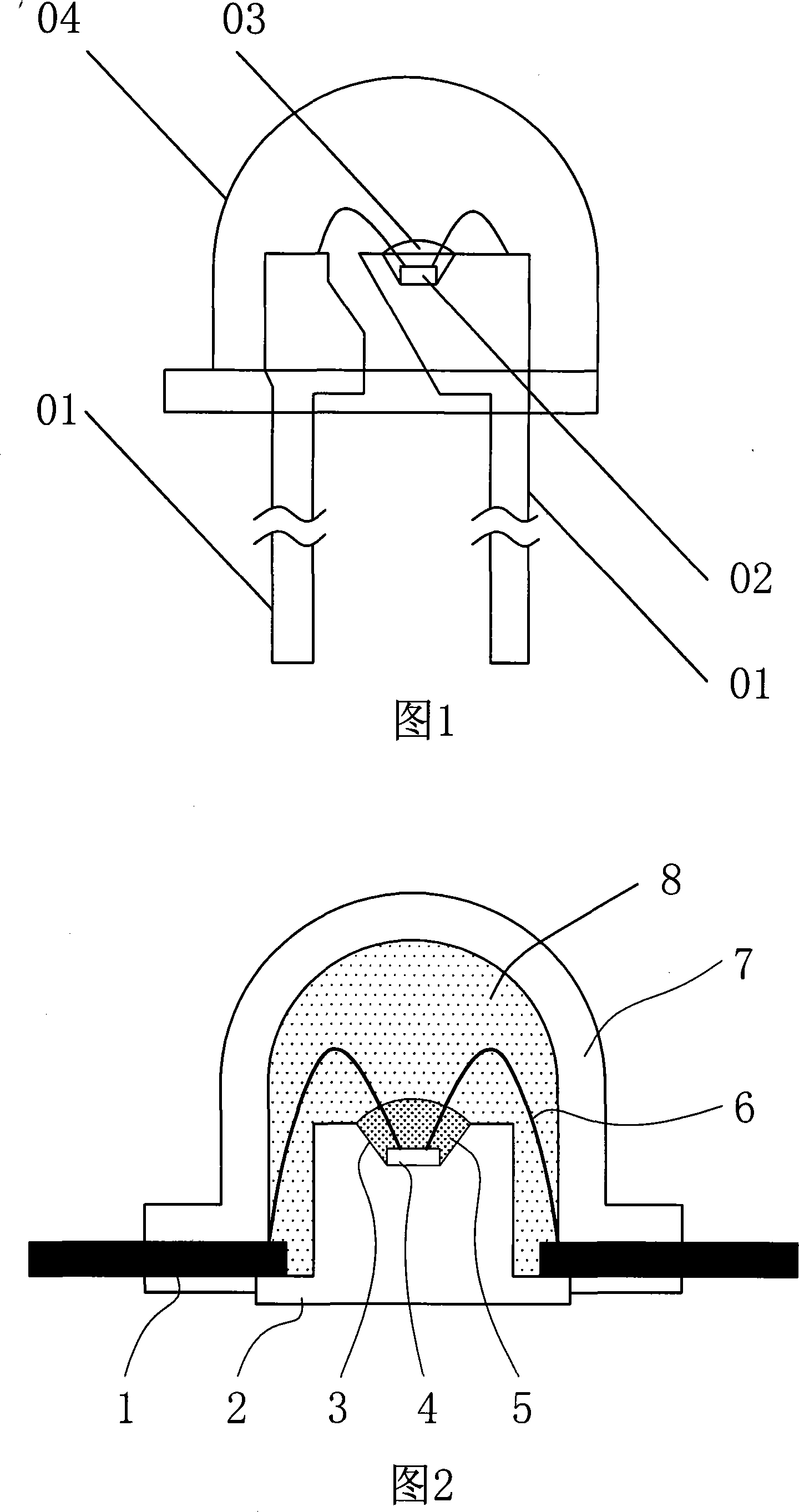
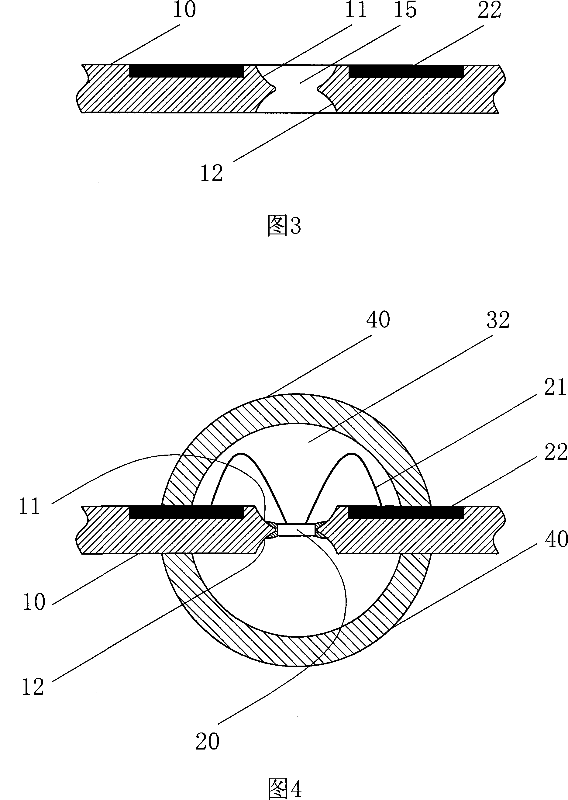
[0030] Embodiment 1: Refer to Fig. 3-4: the light-emitting diode of two-way light emission and heat dissipation is that the positive and negative electrodes on the light-emitting diode chip 20 are respectively drawn out with lead wires 21 and connected with the guide pins 22 extending outside the lens cover 40, the lens The cover 40 can cover the chip 20 , and at least one chip 20 is fixed in the through hole 15 on the substrate 10 .

[0031] The above-mentioned wafer 20 is a wafer of red light, yellow light, blue light, green light or orange light.

[0032] The upper and lower ends of the above-mentioned through hole 15 are two outwardly expanding cup-shaped bottomless grooves 11 , 12 .

[0033] The above-mentioned substrate 10 is made of PCB-based or copper-based or aluminum-based or iron-based materials.

[0034] A cavity 32 may be provided between the lens cover 40 and the medium 30, and the cavity 32 is filled with an inert gas of nitrogen, helium, neon, argon, or xenon....

Embodiment 2

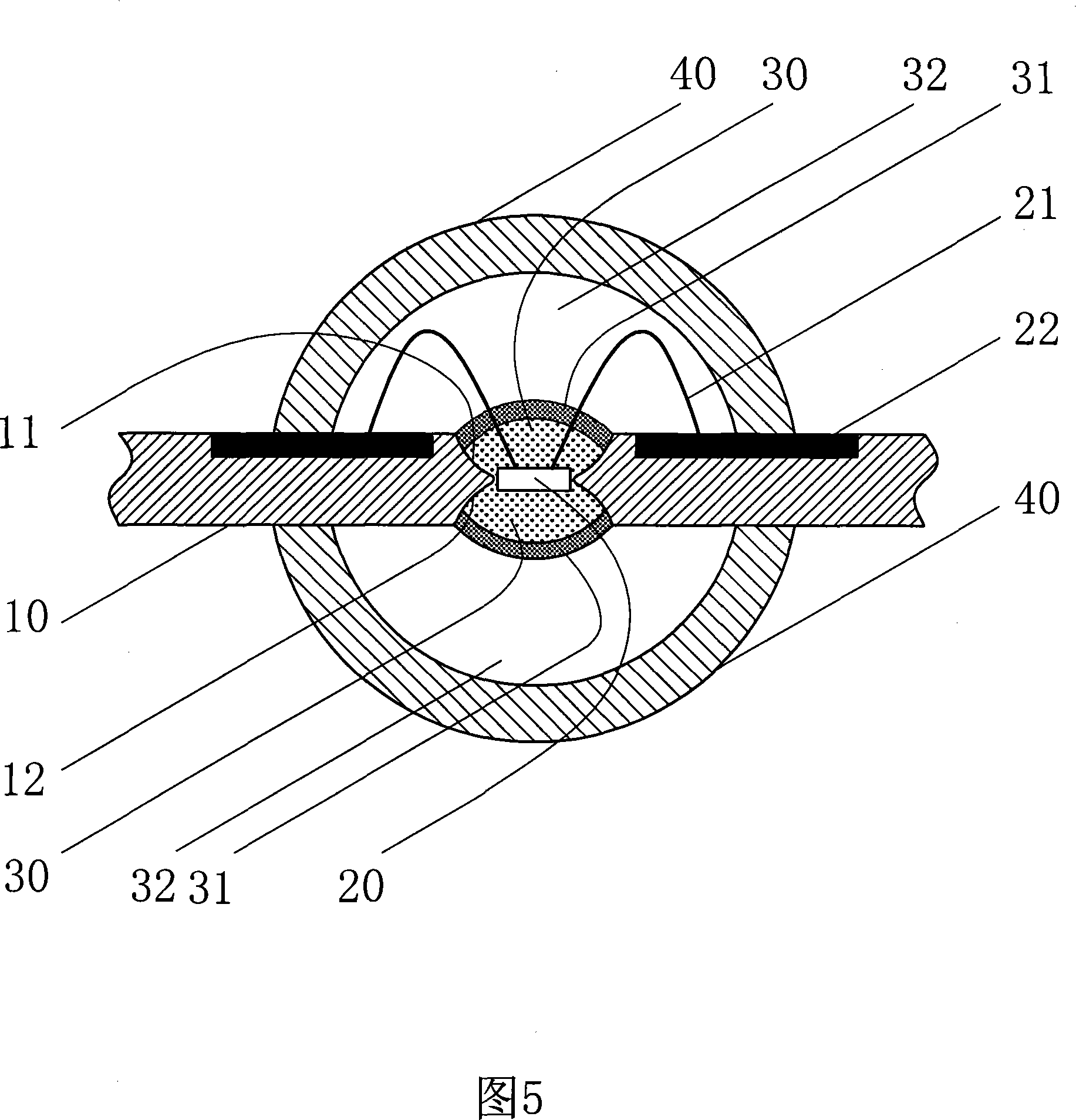
[0036] Embodiment 2: referring to Fig. 5: the basic structure is basically the same as that of Embodiment 1, except that when the wafer 20 is a blue light chip, a light-transmitting, heat-insulating medium 30 is arranged on the outer surface of the blue light chip, and on the outer surface of the medium 30 or a lens A layer of phosphor powder 31 is disposed on the cover 40 .

[0037] The above medium 30 is made of heat-insulating, light-transmitting, UV-resistant silica gel or epoxy resin or ceramics or optical plastics or optical glass materials.

[0038] The phosphor powder 31 disposed on the lens cover 40 is arranged in the interlayer of the lens cover 40 or the inner surface of the lens cover or the outer surface of the lens cover or mixed in the material for making the lens cover 40 .

Embodiment 3

[0039] Embodiment 3: Referring to Fig. 6: the basic structure is basically the same as that of Embodiment 2, except that the above-mentioned one layer of fluorescent powder 31 is arranged on the lens cover 40, that is, arranged in the interlayer of the lens cover 40, of course, the above-mentioned fluorescent powder It is arranged in the interlayer of the lens cover or the inner surface of the lens cover or the outer surface of the lens cover or mixed in the material for making the lens cover.


PUM


Abstract

The invention relates to a light-emitting diode (LED) technology, namely, a LED of bidirectional luminescence and heat radiation. The lead wire are led from the positive and negative electrodes on the LED chips respectively and connected to the guide pin extends to the outside of the lens cap. The chip can be covered by the lens cap, at least one chip is fixed in the through hole on the substrate, but also the transparent and adiabatic medium is positioned on the external surface of the chip, and then the external surface of the medium or the lens cap is equipped with a phosphor layer. The invention has the advantages that lighting effect of LED can increase 16 to 36 percent due to the bidirectional luminescence of the chip of the invention, due to separation of the phosphor and the chip in white LED, the phosphor is not easily heated, aged and carbonized and blacken, the color temperature and the illumination intensity is stable. The luminous flux of the product is still more than 90 percent of the initial luminous flux and the product can be made into various light-emitting LED light after aging test of 5000 hours.

Description

Technical field: [0001] The invention relates to the technical field of light-emitting diodes (LEDs), in particular to a light-emitting diode with bidirectional light emission and heat dissipation. Background technique: [0002] Light-emitting diode (LED) is a semiconductor solid light-emitting device. It uses a solid semiconductor wafer as a light-emitting material. When a forward voltage is applied to both ends, the carriers in the semiconductor recombine to cause photon emission to generate light. It is the most The popular light source technology, the characteristics of LED light source are: energy saving: energy consumption is reduced by 80% compared with incandescent lamps with the same light effect; using low voltage power supply (between 6-24V), good safety; small size, can be prepared into various Shaped devices; long life; fast response time: the response time of incandescent lamps is milliseconds, and the response time of LED lamps is nanoseconds; no harmful metal...

Claims


Application Information

Patent Timeline
Patent Type & Authority Applications(China)
IPC IPC(8): H01L33/00H01L23/498H01L23/13F21V23/00F21V13/02F21V3/04F21V29/00F21V29/503H01L33/48H01L33/50H01L33/64
CPCH01L2224/48091H01L2224/48247H01L2224/48257H01L2224/8592H01L2924/181
Inventor 邹本壮
Owner CHANG HSIN HIGH INTENSITY LED DONG GUAN
Why Eureka
Try Eureka