
Method of producing optical film, optical film, polarizer plate, transfer material, liquid crystal display device, and polarized ultraviolet exposure apparatus

An optical film and manufacturing method technology, applied in optics, polarizing elements, optical elements, etc., can solve the problems of affecting the optical characteristics of optical films, affecting molecular orientation, insufficient film strength, etc., and achieving good viewing angle characteristics and high productivity. Effect

Inactive Publication Date: 2008-02-27
FUJIFILM CORP
View PDF83 Cites 67 Cited by
  • Summary
  • Abstract
  • Description
  • Claims
  • Application Information

AI Technical Summary

Problems solved by technology

[0009] If the irradiation amount of polarized ultraviolet rays used in the production of the above-mentioned two-way retardation plate, etc. is small, the strength of the cured film will be insufficient, or when the molecular orientation of the liquid crystal is accompanied by the curing, the molecular orientation will be affected. As a result, it also affects the optical properties of the produced optical film, etc.

Method used


Image

  • Method of producing optical film, optical film, polarizer plate, transfer material, liquid crystal display device, and polarized ultraviolet exposure apparatus
  • Method of producing optical film, optical film, polarizer plate, transfer material, liquid crystal display device, and polarized ultraviolet exposure apparatus
  • Method of producing optical film, optical film, polarizer plate, transfer material, liquid crystal display device, and polarized ultraviolet exposure apparatus

Examples


Embodiment 1~5 and comparative example 1

[0240] [Examples 1 to 5 and Comparative Example 1: Production of optical film]

[0241] (Production of transparent support S-1)

[0242] Fujitac TD80UF (manufactured by Fuji Photo Film Co., Ltd., Re=3nm, Rth=50nm), which is a commercially available cellulose acetate film, was used as the transparent support S-1.

[0243] (Preparation of coating liquid AL-1 for alignment layer)

[0244] The following composition was prepared, filtered through a polypropylene filter with a pore diameter of 30 μm, and used as the coating liquid AL-1 for the alignment layer. As the modified polyvinyl alcohol, the one described in JP 9-152509 A was used.

[0245] Composition of coating solution for alignment layer (mass%)

[0246] Modified polyvinyl alcohol AL-1-1 4.01

[0247] Water 72.89

[0248] Methanol 22.83

[0249] Glutaraldehyde (crosslinking agent) 0.20

[0250] Citric acid 0.008

[0251] Monoethyl citrate 0.029

[0252] Diethyl citrate 0.027

[0253] Triethyl citrate 0.006

[0254] [化10]

[0...

Embodiment 16

[0362] [Example 16: Production of Polarizing Plate with Optical Compensation Film]

[0363] The optical film of Example 1 manufactured above and the commercially available FujitacTD80UF (manufactured by Fujifilm Co., Ltd., Re=3nm, Rth=50nm) were immersed in a 1.5mol / L sodium hydroxide aqueous solution at 55°C. 2 minute. Next, it was washed in a water bath at room temperature, and neutralized with 0.05 mol / L sulfuric acid at 30°C. Wash it again in a water bath at room temperature, and then dry it with warm air at 100°C. Then, the two saponified films are used as the protective film of the polarizer, and the two sides of the polarizing film are attached with a roll-to-roller using a polyvinyl alcohol-based adhesive to produce a monolithic type. Polarizer.

Embodiment 17

[0364] [Example 17: Production and evaluation of VA-LCD liquid crystal display device]

[0365] Peel off the polarizers on the upper and lower sides of a commercially available VA-LCD (SyncMaster 173P, manufactured by Samsung Electronics Co., Ltd.), and bond the usual polarizers on the upper side with an adhesive, and bond the polarizers made in Example 16 on the lower side. In the polarizing plate with an optical film of Example 1, the optically anisotropic layer was used as the glass surface of the liquid crystal cell substrate to produce the liquid crystal display device of the present invention. In FIG. 11, a schematic cross-sectional view of the produced liquid crystal display device is shown together with the angular relationship of the optical axis of each layer. In Figure 11, 41 is a polarizing layer, 42 is a transparent support, 43 is an orientation layer, 44 is an optically anisotropic layer (42 to 44 are optical films manufactured in Example 1), and 45 is a polarizer pr...


PUM

PropertyMeasurementUnit
thicknessaaaaaaaaaa
heightaaaaaaaaaa
particle sizeaaaaaaaaaa

Abstract

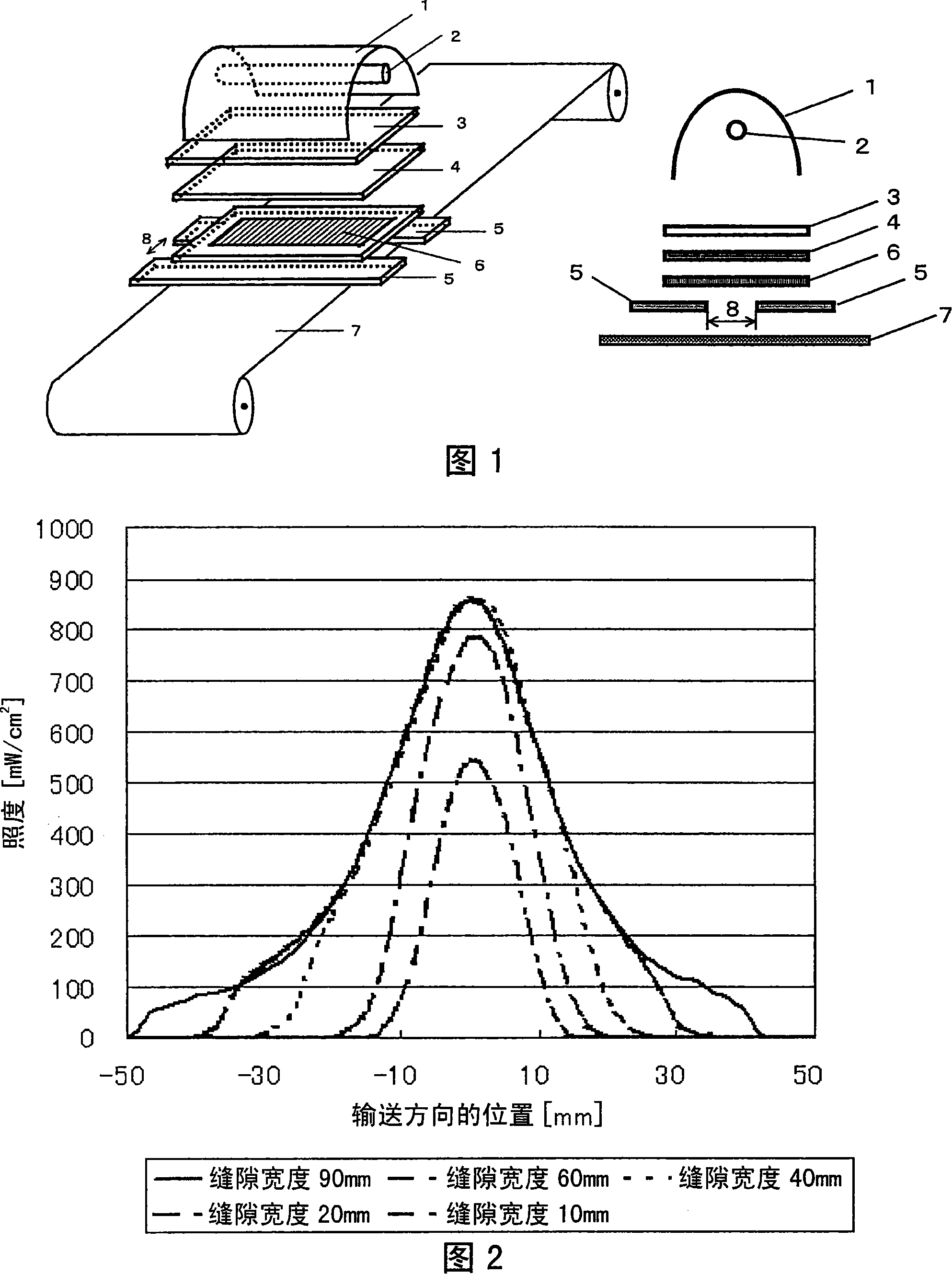
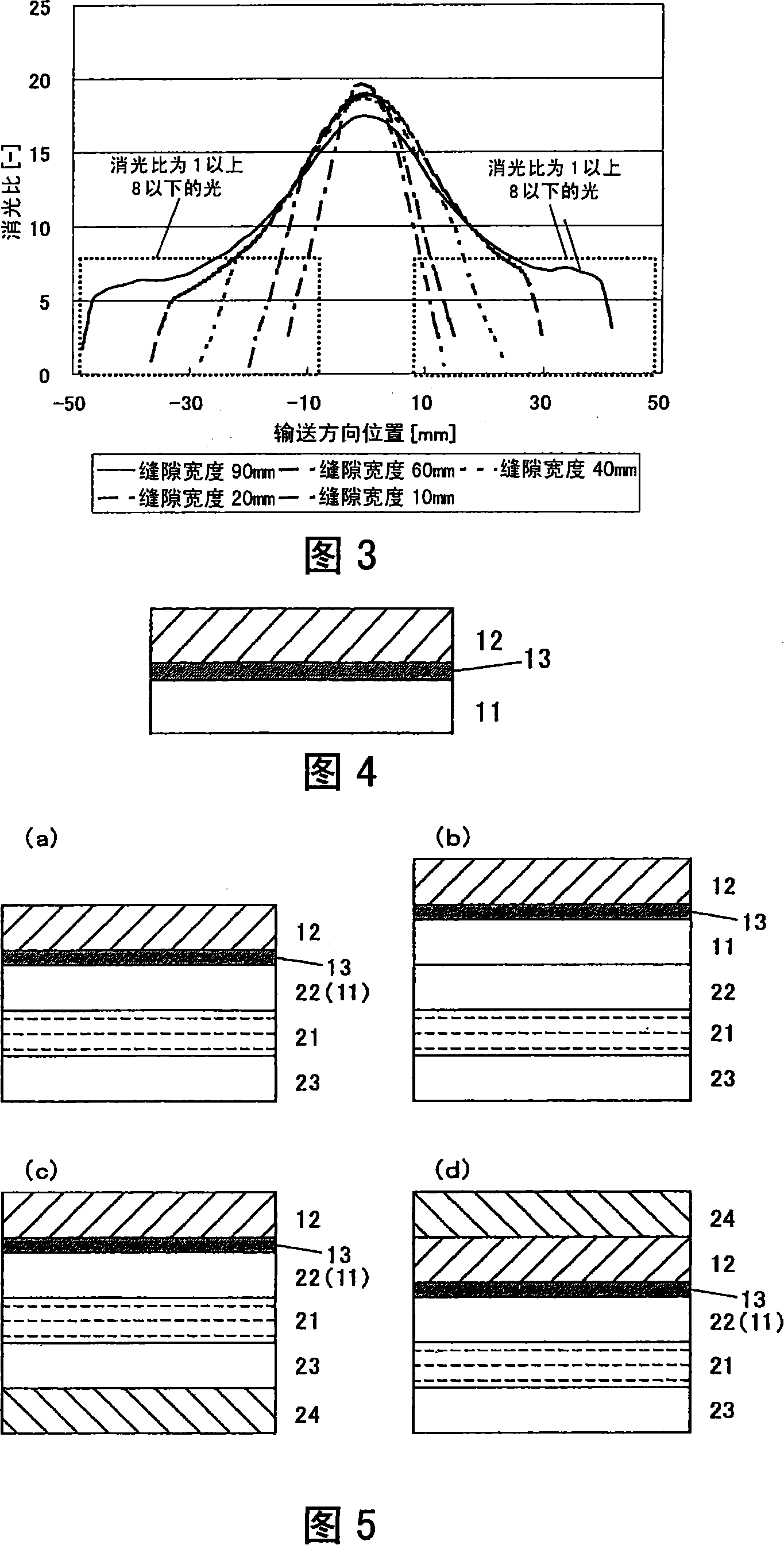
The present invention provides a method for producing an optical film exhibiting excellent optical characteristics and film strength with high productivity in a production method of an optical film including a step of irradiating polarized ultraviolet rays. The method for producing an optical film is characterized in that it is a method for producing an optical film comprising the following steps (1) to (3) in the order of (1) to (3): (1) A layer composed of a polymerizable composition containing a polymerizable liquid crystal compound and a dichroic polymerization initiator is formed on the surface; (2) the molecules of the polymerizable liquid crystal compound in the layer are formed into a first alignment state; (3) The layer is irradiated with polarized ultraviolet rays to polymerize the polymerizable liquid crystal compound, and fix the molecules of the polymerizable liquid crystal compound in the second alignment state to form an optically anisotropic layer. Exposure to area (J / cm 2 ), the proportion of polarized ultraviolet rays with an extinction ratio of 1 to 8 is 15% or less.

Description

Technical field [0001] The present invention relates to a method for manufacturing an optical film and a polarized ultraviolet exposure device useful in the method. In addition, the present invention also relates to an optical film manufactured by the above method, a polarizing plate, a transfer material, and a liquid crystal display device using the optical film. In particular, it relates to an optical film that contributes to improving the viewing angle characteristics of a vertical alignment type liquid crystal display element, and a liquid crystal display device with improved viewing angle characteristics. Background technique [0002] As a display device used in OA equipment such as word processors, notebook computers, and personal computer monitors, portable terminals, televisions, etc., CRTs (Cathode Ray Tubes) are currently mainly used. In recent years, liquid crystal display devices (LCDs) have been widely used instead of CRTs due to their thinness, light weight, and low...

Claims


Application Information

Patent Timeline
Patent Type & Authority Applications(China)
IPC IPC(8): G02B1/04G02B5/30G02F1/1335
CPCG02F2413/07G02F2413/09G02F2001/133633G02F2001/133565G02B5/3016G02F1/13363G02F2202/40G02F2413/02G02F1/133565G02F1/133631G02F1/133633G02B5/30G02F1/1337
Inventor 水谷英章川西直之佐野贵之
Owner FUJIFILM CORP
Learn More