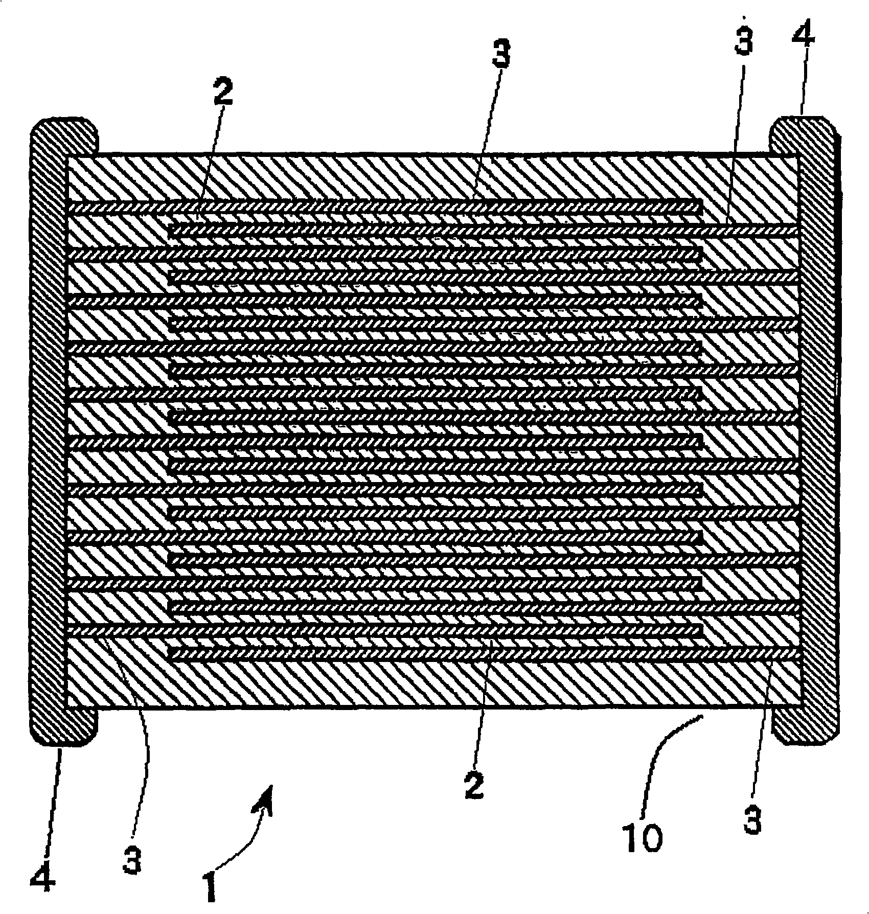
COG dielectric composition for use with nickel electrodes
A technology of dielectric and composition, applied in the field of zirconium titanate-based dielectric composition, can solve problems such as capacitance aging, and achieve the effects of stable dielectric constant, small dielectric loss and high reliability
- Summary
- Abstract
- Description
- Claims
- Application Information
AI Technical Summary
Problems solved by technology
Method used
Image
Examples
Embodiment 1
[0051] The dielectric composition referred to as Precursor 1 was formed by mixing, compounding and / or milling the appropriate amount of oxides as shown in Table 6 in water. Mix the powder with 1% of C (a polymer suspending agent available from RT Vanderbilt Co., Inc., Norwalk, Connecticut) was mixed. Bead mill the mixed powder to particle size D with 0.5mm YTZ (stabilized yttrium zirconia) 50 is about 0.65 microns. The powder was calcined at 1200°C for 5 hours. Then, the calcined powder was pulverized by a conventional method to obtain a precursor 1 .
[0052] Table 6. Formulation of Precursor 1 before calcination
[0053] SrCO 3
ZrO 2
TiO 2
wt%
54.901
43.761
1.337
[0054] Additionally, after calcination, the composition of Precursor 1 can be represented by the following formula: SrZr 0.955 Ti 0.045 o 3 . According to the formula in Table 7, 2MgO·3B 2 o 3 (as Mg(OH) 2 and H 3 BO 3 combination) was added t...
Embodiment 2
[0068] According to Table 11, the Mg(OH) 2 , CaCO 3 、Al 2 o 3 and SiO 2 The mixture of is added to the precursor 1 as a sintering aid (after sintering to efficiently produce MgO-CaO-Al 2 o 3 -SiO 2 ). The powder was processed according to Example 1.
[0069] Table 11. Recipe for the dielectric of Example 2 prior to firing
[0070] precursor 1
Mg(OH) 2
CaCO 3
Al 2 o 3
SiO 2
wt%
97.812
0.257
0.257
0.579
1.096
[0071] The powder of Example 2 has the general formula which can alternatively be expressed as: 98.003 wt% SrZr 0.955 Ti 0.045 o 3 +0.178wt% MgO+0.144wt% CaO+0.579wt% Al 2 o 3 +1.096wt% SiO 2 . Example 2 has the formulation of Table 12 when expressed as a simple oxide.
[0072] Table 12. Oxide composition of the dielectric powder of Example 2
[0073] SrO
ZrO 2
TiO 2
MgO
CaO
Al 2 o 3
SiO 2
wt%
45.156
51.281
...
Embodiment 3-14
[0078] Various amounts of mixtures including MgO, CaO, Al 2 o 3 , SiO 2 And / or any one or all of SrO. Since the sintering aid in Examples 12, 13 and 14 also contained SrO, the total SrO in these examples was derived from both Precursor 1 and the sintering aid. For Examples 3-14, the total weight of Precursor 1 is the first three columns (SrO, ZrO 2 and TiO 2 )Sum. The composition and MLCC electrical properties of Example 2 are also included in Tables 14 and 15 for ease of comparison.
[0079] Table 14. Oxide composition (expressed in wt %) of the powders of Examples 2-14
[0080] implement
[0081] The final powders of Examples 3-14 were processed according to the procedure of Example 1 to prepare MLCC flakes for electrical testing. Firing conditions and electrical properties are summarized in Table 15. Each MLCC was fired for 2 hours.
[0082] Table 15. Firing conditions and electrical properties of MLCCs of Examples 2d-15
[0083] Example
[008...
PUM
| Property | Measurement | Unit |
|---|---|---|
| thickness | aaaaa | aaaaa |
| diameter | aaaaa | aaaaa |
| thickness | aaaaa | aaaaa |
Abstract
Description
Claims
Application Information
 - R&D
- Intellectual Property
- Life Sciences
- Materials
- Tech Scout
- Unparalleled Data Quality
- Higher Quality Content
- 60% Fewer Hallucinations
Browse by: Latest US Patents, China's latest patents, Technical Efficacy Thesaurus, Application Domain, Technology Topic, Popular Technical Reports.
© 2025 PatSnap. All rights reserved.Legal|Privacy policy|Modern Slavery Act Transparency Statement|Sitemap|About US| Contact US: help@patsnap.com

