

Electrostatic resistant film and product including the same
An antistatic film and product technology, applied in the direction of static electricity, packaging item type, film/sheet adhesive, etc., can solve problems such as difficulty in observing components, poor transparency of cover tape, and component contamination
- Summary
- Abstract
- Description
- Claims
- Application Information
AI Technical Summary
Problems solved by technology
Method used
Image

Examples
Embodiment 1
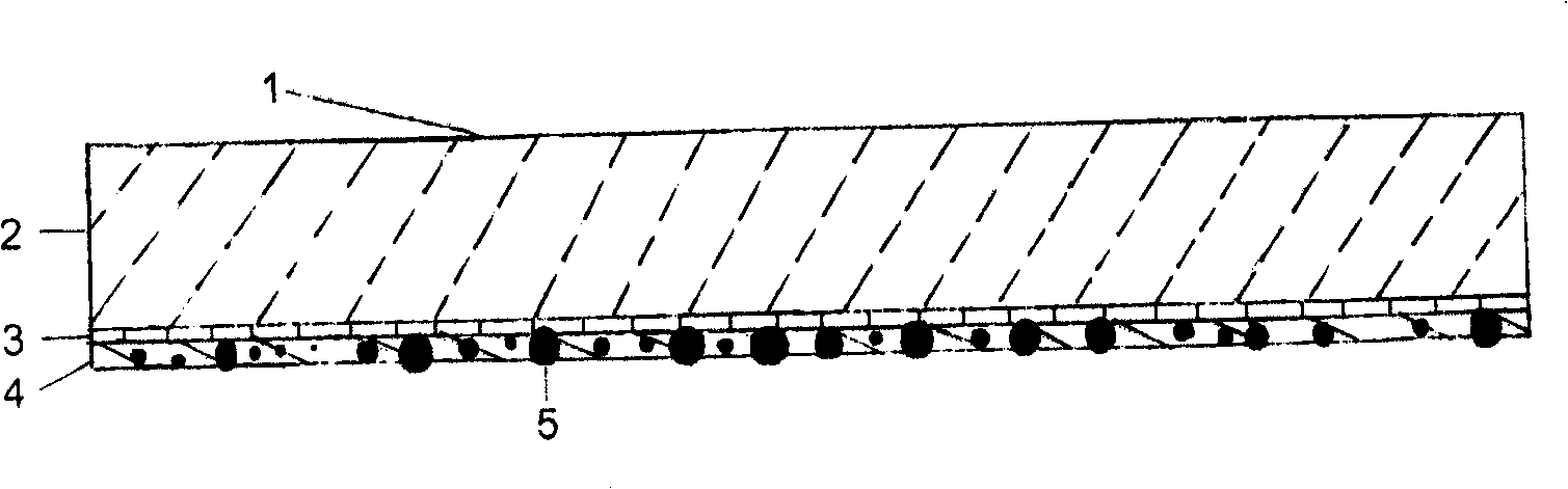
[0051] figure 1 Shown is a schematic cross-sectional view of a transparent low-contamination antistatic film 1 according to an embodiment of the present invention. The base film 2 is a biaxially stretched BOPP film (also polypropylene, polyethylene, polycarbonate, celluloid, nylon, polyester, etc.), and one layer of conductive layer 3 is arranged on one side of the base film 2. The conductive layer 3 is a metal layer (it may also be a metal oxide layer), which can be realized by evaporation or magnetron sputtering. On the other side of the conductive layer 3 relative to the base film is a protective layer 4, the protective layer 4 is used to protect the conductive layer 3, and the protective layer contains particles 5 used to suppress the decline in the surface conductivity of the film, the particles 5 Mainly used to provide electrical continuity in the Z direction. The film has good transparency, low pollution, wear resistance and permanent antistatic properties.
Embodiment 2
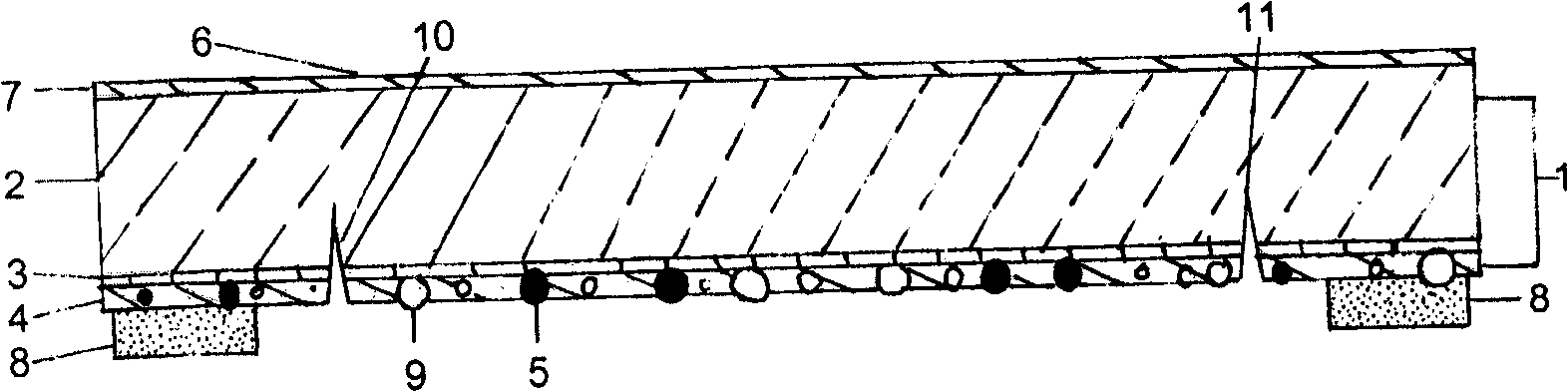
[0053] figure 2 Shown is a schematic cross-sectional view of a cover tape 6 according to one embodiment of the present invention.
[0054] The cover tape 6 includes a base film 2 , a conductive layer 3 , a protective layer 4 , a release agent layer 7 and a strip-shaped adhesive layer 8 . The base film 2 is a biaxially stretched BOPP film with a thickness of 50 microns. On one surface of the base film 2, there is a conductive layer 3, which is a metal layer. There is a protective layer 4 on the other side of the conductive layer 3 relative to the base film, and the protective layer 4 is used to protect the conductive layer 3. The protective layer is polyurethane containing particles 5 used to suppress the decline in the surface conductivity of the film. Coating, particles 5 are mainly used to provide electrical conductivity in the Z direction. Also contain anti-adhesive filler 9 in protective layer 4, this anti-adhesive filler 9 and particle 5 can be the same material (see ...
Embodiment 3
[0056] The cover tape 6 of the present invention can be used in a carrier tape / cover tape system 14 for component packaging. Figure 4 A perspective view of a carrier tape / cover tape system comprising a carrier tape 15 and a cover tape 6 is shown. The carrier tape 15 has a pair of long sides 16 and one or more recesses 17 . A component 18 can be placed in the recess 17 . After the components 18 are put into the concave portion 17 of the carrier tape, the cover tape 6 is glued to the carrier tape through the long side 16 of the carrier tape so as to cover the concave portion 17 . In this way, components 18 can be loaded between the carrier tape 15 and the cover tape 6 . In order to open the cover tape 6 and transfer the components, the cover tape is finally stripped from the carrier tape / cover tape system 14 . Such as Figure 4 As shown, the middle portion 13 of the cover tape 6 (located between the two tear grooves 12) is peeled off, and the extension 19 of the cover tape ...
PUM
| Property | Measurement | Unit |
|---|---|---|
| Thickness | aaaaa | aaaaa |
| Thickness | aaaaa | aaaaa |
| Thickness | aaaaa | aaaaa |
Abstract
Description
Claims
Application Information