Novel organic electroluminescent compounds and organic electroluminescent device using the same

A compound and luminescent technology, applied in electroluminescent light sources, indium organic compounds, platinum group organic compounds, etc., can solve the problem of not being able to provide pure red at the same time

Inactive Publication Date: 2009-10-07
GRACEL DISPLAY INC
View PDF0 Cites 14 Cited by
  • Summary
  • Abstract
  • Description
  • Claims
  • Application Information

AI Technical Summary

Problems solved by technology

[0009] However, materials formed by iridium complexes can only be applied to small displays because they cannot provide pure red color and high luminous efficiency at the same time (the application in medium-to-large-sized OLED panels is limited), and for medium-to-large-sized OLED panels A higher level of EL properties than known materials is actually required

Method used


Image

  • Novel organic electroluminescent compounds and organic electroluminescent device using the same
  • Novel organic electroluminescent compounds and organic electroluminescent device using the same
  • Novel organic electroluminescent compounds and organic electroluminescent device using the same

Examples


preparation example 1

[0186] [Preparation Example 1] Preparation of Compound (1)

[0187]

[0188] Preparation of compound (A)

[0189] 3-Aminonaphthalene-2-carboxylic acid (1.0 g, 5.4 mmol) was dissolved in THF (50 mL), and the temperature of the solution was lowered to 0°C. Phenyllithium (11.9 mL, 21.4 mmol) was slowly added to the solution. After stirring for 2 hours, aqueous ammonium chloride solution was added to the reaction mixture to quench the reaction. The resulting mixture was extracted with diethyl ether, and the extract was filtered under reduced pressure. Purification by silica gel column chromatography gave Compound (A) (0.79 g, 60%).

[0190] Preparation of compound (B)

[0191] Add compound (A) (1.29 g, 5.24 mmol), acetophenone (0.55 ml, 4.76 mmol), acetic acid (7.13 ml) and sulfuric acid (0.04 ml) in a reaction vessel, under argon atmosphere, reflux conditions Stir down. When the reaction was completed, the reaction mixture was cooled to room temperature, and an excess ...

Embodiment 1

[0311] [Example 1] Manufacture of OLED (1)

[0312] OLED devices were fabricated using the red phosphorescent compounds of the present invention.

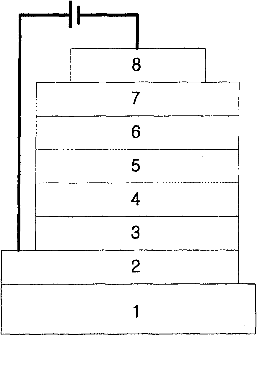
[0313] First, a thin film (15Ω / □) (2) of transparent electrode ITO made of glass for OLED (manufactured by Samsung Corning) (1) was ultrasonically cleaned with the following substances in order: trichloroethylene, acetone , ethanol, and distilled water, store in isopropanol until use.

[0314] Then, the ITO substrate is installed in the substrate folding machine of the vacuum vapor deposition equipment, and 4,4', 4 "-three (N, N-(2-naphthyl)-phenylamino) triphenylamine (2 -TNATA) is put into the chamber of this vacuum vapor deposition equipment, then this chamber ventilation makes indoor vacuum up to 10 -6 support. A current is applied in the chamber to evaporate 2-TNATA, thus vapor-depositing a 60 nm thick hole injection layer on the ITO substrate (3)

[0315]

[0316] Then, add N, N'-bis(α-naphthyl)-N, N'-diphenyl-4,4'-dia...

Embodiment 2

[0323] [Example 2] Manufacture of OLED (2)

[0324] After forming the hole injection layer and the hole transport layer in the manner of Example 1, the electroluminescence layer was vapor-deposited as follows. In another chamber of the vacuum vapor deposition apparatus, H-5 was added as an electroluminescence host material, and a phosphorescent compound of the present invention (Compound 61) was added in another chamber. The two substances are doped by evaporation at different rates, and an electroluminescent layer (5) with a thickness of 30 nanometers is vapor-deposited on the hole transport layer. Based on the host, the suitable doping concentration is 4-10% by weight. Then, a hole blocking layer, an electron transport layer, and an electron injection layer were vapor-deposited in the same manner as in Example 1, and an Al cathode was vapor-deposited with a thickness of 150 nanometers using another vacuum vapor deposition apparatus to manufacture an OLED.

[0325]

[03...


PUM


Abstract

The present invention relates to novel organic electroluminescent compounds, and organic electroluminescent devices comprising the same. Specifically, the novel organic electroluminescent compounds according to the invention are characterized in that they are represented by Chemical Formula (1).

Description

technical field [0001] The present invention relates to a novel organic electroluminescent compound and an organic electroluminescent device using the compound as an electroluminescent dopant. More specifically, the present invention relates to novel iridium compounds having highly efficient red phosphorescent properties, which can be used as materials for forming electroluminescent layers of electroluminescent devices, and to useful methods of using the compounds as electroluminescent dopants. Electromechanical Luminescent Devices. Background technique [0002] The most important factor determining the luminous efficiency of an OLED (Organic Light Emitting Diode) is the electroluminescent material. Although fluorescent materials have been widely used as electroluminescent materials so far, from the perspective of electroluminescent mechanism, the development of phosphorescent materials is one of the best methods to theoretically increase the luminous efficiency by four tim...

Claims


Application Information

Patent Timeline
Patent Type & Authority Applications(China)
IPC IPC(8): C07F15/00C07D221/08C09K11/06H01L51/50H01L51/54H01L51/42H01L51/46
CPCH01L51/0085C07F15/0033H01L51/0084H05B33/14H01L51/0092H01L51/0077C07D221/08H01L51/0081C09K11/06Y02E10/549H01L51/5016C09K2211/185C09B15/00C09B23/145C09B57/00C09B57/10C09B23/105H10K85/30H10K85/324H10K85/341H10K85/342H10K85/381H10K50/11H10K2101/10
Inventor 赵英俊权赫柱金奉玉金圣珉尹胜洙
Owner GRACEL DISPLAY INC
Why Eureka
Try Eureka