
Hydrogen production system employing reforming technology

A reforming hydrogen production and reformer technology, applied in hydrogen, sustainable manufacturing/processing, inorganic chemistry, etc., can solve the lack of flexibility in temperature adjustment of catalytic reaction units, the inability to ensure the safety of reactors and heat exchangers, Heat cannot be transferred and other problems, to achieve the effect of ensuring power generation performance, not easy to sinter, and reasonable structure

Active Publication Date: 2010-01-13
HANERGY TECH
View PDF3 Cites 14 Cited by
  • Summary
  • Abstract
  • Description
  • Claims
  • Application Information

AI Technical Summary

Problems solved by technology

[0005] Patent CN1567637 invented a fuel cell fuel supply device, the fuel supply device includes fuel tanks, reformers, reactors, power converters, compressors and control devices, with the characteristics of high energy utilization efficiency, but the system in the catalytic reaction Lack of flexibility in terms of temperature regulation of the unit, while heat cannot be transferred in time across the granular catalyst bed
Patent CN1284721 invented a methanol reforming hydrogen production system. The reforming reactor in this system adopts a plate-fin structure, which is coupled with the processes of catalytic combustion heat supply, evaporation and reforming reaction. It has the advantages of high efficiency and compactness, but In the start-up phase of the system, the catalytic combustion unit uses H 2 as fuel, thus requiring additional storage of H 2
At the same time, there may be local concentration of fuel and oxidant (air or oxygen) in the catalytic combustion unit, so that it is possible to release a large amount of heat locally, causing the fins to be burned through.
Patent CN2668600 uses a plate-fin reforming reactor and a plate-fin heat exchanger, but for the heating device, this patent uses a heater, which cannot guarantee the safety of the reactor and heat exchanger, and is relatively thin The fins are still easy to be burned through. In addition, the design of the entire system has room for improvement in terms of full energy utilization.

Method used


Image

  • Hydrogen production system employing reforming technology
  • Hydrogen production system employing reforming technology
  • Hydrogen production system employing reforming technology

Examples


Embodiment 1

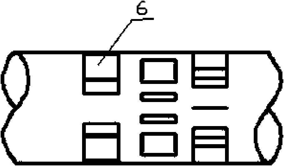
[0037] A reforming hydrogen production system, such as figure 1 , 2 , 3, including a heat supply unit, a reformer 6, and a CO purification and removal unit, the outlet of the reformer 6 communicates with the inlet of the CO purification and removal unit through a heat exchanger 12, and the outlet of the CO purification and removal unit passes through a heat exchange The device 16 communicates with the hydrogen inlet of the fuel cell 17; the heating unit is a two-layer sleeve structure, the outer cavity is the combustion heating cavity 2, and the inner cavity is the raw material heating cavity 1, and the combustion heating cavity 2 is provided with methanol Inlet 4, air inlet 20 and hydrogen inlet 5, the tail gas outlet 18 of the fuel cell 17 communicates with the hydrogen inlet 5 on the combustion heating chamber 2; the outlet of the raw material heating chamber 1 communicates with the inlet of the reformer 6; Three groups of fins 3 are axially arranged on the inner wall of t...

Embodiment 2

[0054] The system structure and operation method are basically the same as in Embodiment 1, except that two groups of ribs 3 are axially arranged on the inner wall of the raw material heating chamber 1, and the groups are staggered radially along the central axis of the chamber, and each group is 5 pieces , the adjacent fins between each group are staggered at an angle of 36° in the radial direction along the central axis of the cavity; the oxidant gas is oxygen; the CO purification and removal unit is a CO methanation reactor; the The regenerator is quartz sand; each fin has 12 holes, and the area of ​​the holes is 60% of the area of ​​the fin.

Embodiment 3

[0056] The system structure and operation method are basically the same as in Embodiment 1, except that each fin has two holes, and the area of ​​the holes is 10% of the area of ​​the fin.

[0057] The hydrogen-rich fuel for combustion and raw materials is not limited to methanol in the above examples, but can also be methane, dimethyl ether, hydrogen, ethanol, natural gas, city gas, liquefied petroleum gas, gasoline, kerosene or diesel oil, etc. Embodiment, wherein, the hydrogen-rich fuel used as a raw material can also be a methanol solution.


PUM


Abstract

The invention discloses a hydrogen production system employing reforming technology, in particular to a sleeve type hydrogen enriched fuel hydrogen production system employing reforming technology with highly efficient heat and mass transfer. The system comprises a heat supply unit, a reformer and a CO purification and elimination unit; wherein, the outlet of the reformer is communicated with theinlet of the CO purification and elimination unit through a heat exchanger, the outlet of the CO purification and elimination unit is communicated with the hydrogen inlet of a fuel cell; the heat supply unit has a two-layer sleeve barrel structure, the outer cavity is a combustion heat-providing cavity, the inner cavity is a raw material heating cavity, an enriched fuel inlet, an oxidant gas inlet and a hydrogen inlet are arranged on the combustion heat-providing cavity, the exhaust gas outlet of the fuel cell is communicated with the hydrogen inlet on the combustion heat-providing cavity; the outlet of the raw material heating cavity is communicated with the inlet of the reformer; at least two groups of fins are arranged on the inner wall of the raw material heating cavity axially. The system has reasonable structure, the burning and the heating are uniform, the catalyst is not easy to sinter, the performances of the mass transfer and the heat transfer are good and the energy efficiency is high.

Description

technical field [0001] The invention relates to a reforming hydrogen production system, in particular to a hydrogen-rich fuel sleeve type hydrogen-rich fuel reforming hydrogen production system with efficient mass transfer and heat transfer. Background technique [0002] With the rapid development of the fuel cell industry, the upsurge of research and development of hydrogen energy has been promoted. To make extensive use of this new type of energy and power, a reliable and stable source of hydrogen must first be available. Although the industrial-scale coal and natural gas hydrogen production technology is mature, the price of hydrogen will rise sharply after hydrogen compression, storage and transportation. The need for a decentralized hydrogen source for fuel cells of all sizes cannot be met. The use of hydrogen-rich fuels such as hydrocarbons and alcohols to provide hydrogen sources for fuel cells through on-site hydrogen production has become one of the most realistic...

Claims


Application Information

Patent Timeline
IPC IPC(8): C01B3/32
CPCY02P20/10
Inventor 肖钢王义周帅林
Owner HANERGY TECH
Learn More