Active magnetic bearing using bias magnetic flux commonly in radial direction and in axial direction and control method thereof

An active magnetic bearing, axial technology, applied in the direction of shafts and bearings, bearings, mechanical equipment, etc., can solve the failure to make progress in the overall system's compact axial structure and the improvement of the critical speed of the rotor, and the long axial length of the mechanical structure. , large size of the power amplifier, etc., to achieve the effect of compact structure, easy control, and reducing the size of the power amplifier

Inactive Publication Date: 2010-03-10
JIANGSU UNIV
View PDF2 Cites 22 Cited by
  • Summary
  • Abstract
  • Description
  • Claims
  • Application Information

AI Technical Summary

Problems solved by technology

The axial length of the mechanical structure of the 5-DOF magnetic bearing supporting the high-speed motor is relatively long, which has certain restrictions on the increase of the critical speed of the rotor, and a radial magnetic bearing needs two bipolar power amplifiers to drive, and the power amplifier is large in size, High power consumption and high cost, therefore, this magnetic bearing supported high-speed motor structure limits its practical application range in engineering
[0003] At the Seventh International Conference on Magnetic Bearings, C. Redemann of the Swiss Federal Institute of Technology (ETH) in Zurich published a test report on t

Method used


Image

  • Active magnetic bearing using bias magnetic flux commonly in radial direction and in axial direction and control method thereof
  • Active magnetic bearing using bias magnetic flux commonly in radial direction and in axial direction and control method thereof
  • Active magnetic bearing using bias magnetic flux commonly in radial direction and in axial direction and control method thereof

Examples


Embodiment Construction

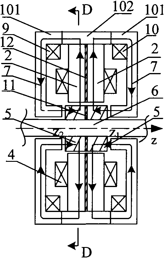
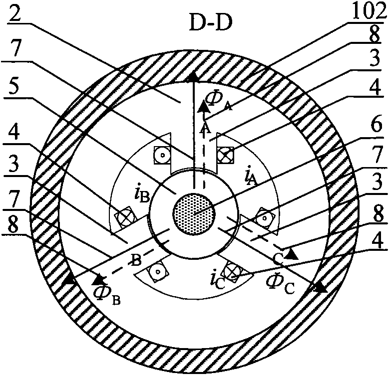
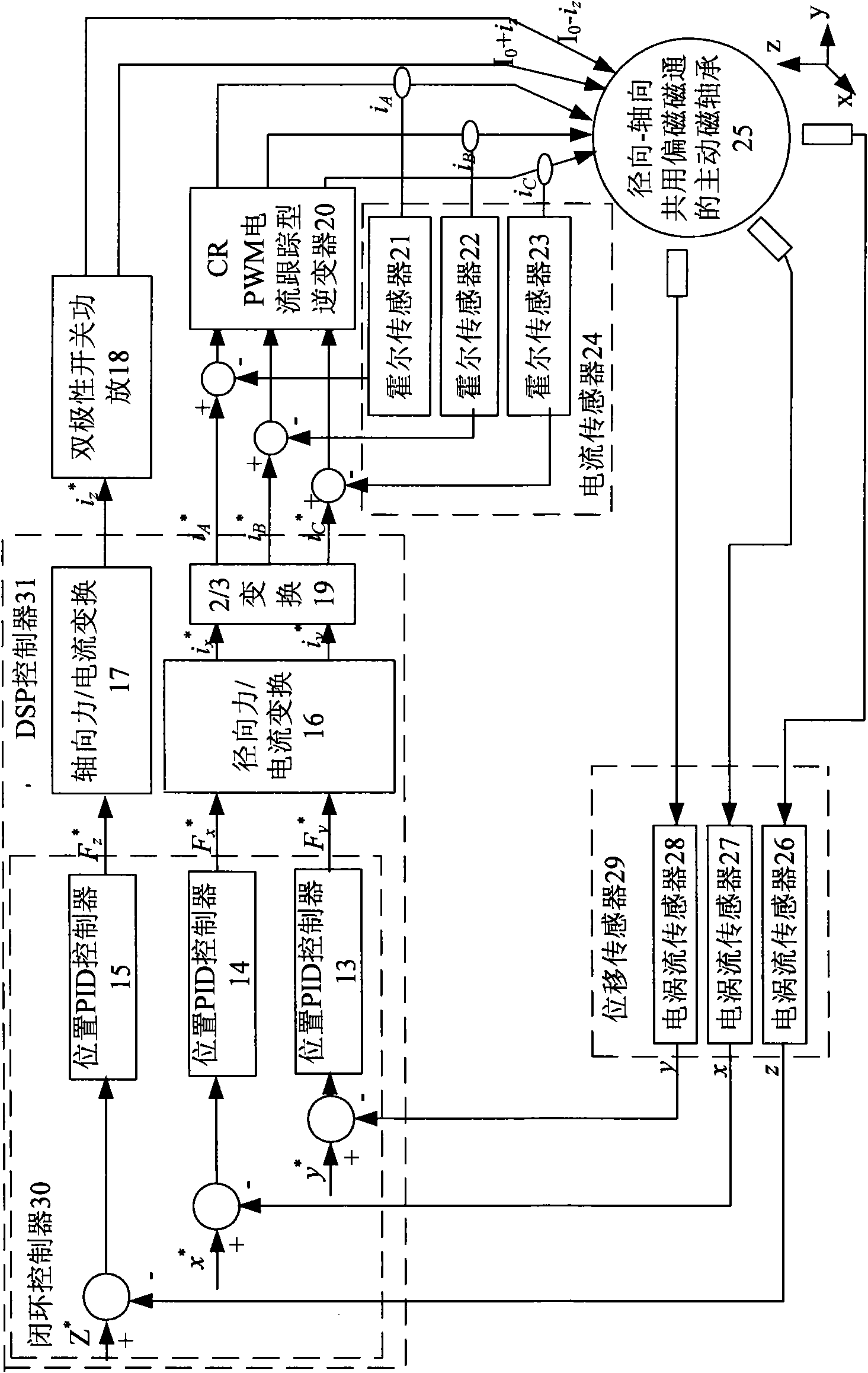
[0021] The present invention firstly designs the structure and magnetic circuit of the active magnetic bearing with radial-axial shared bias flux, and deduces the active magnetic bearing with radial-axial shared bias magnetic flux according to the magnetic field assumption conditions and the equivalent principle of magnetic circuit. The mathematical model of the bearing, and then design the structural parameters and electrical performance parameters of the magnetic bearing according to the mathematical model and combined with the predetermined technical indicators. Based on these structural parameters, use the finite element analysis software Maxwell 3D to further optimize the design of the magnetic bearing structural parameters, and verify the correctness of the structural design principles and magnetic flux distribution. Finally, according to the mathematical model and various actual parameters, the controller is designed and a double closed-loop control system is constructed...


PUM


Abstract

The invention relates to an active magnetic bearing using a bias magnetic flux commonly in radial direction and in axial direction. A bias magnetic current in an axial control coil provides a static bias magnetic flux for the radial direction and the axial direction to generate static bearing capacity, the control current in the axial control coil and in a radial control coil provides the controlmagnetic flux to respectively generate dynamic levitation force in radial direction and in axial direction, and external disturbance is overcome to ensure that a rotor levitates stably at a balance position of the radial direction and the axial direction. A bipolarity switch power amplifier is adopted in axial direction, a CRPWM current following inverter is adopted as a power amplification circuit in radial direction, an eddy current displacement transducer is adopted to detect axial displacement and radial displacement of the rotor and feed the axial displacement and radial displacement backto a DSP controller which is used for carrying out PID operation and providing a corresponding control signal for the power amplification circuit after processing, and the power amplification circuitgenerates control current in a magnetic bearing coil to realize stable levitation of the rotor in axial direction and in redial direction. The active magnetic bearing of the invention has the advantages of small volume, low power amplifier cost and high radial bearing capacity.

Description

technical field [0001] The invention belongs to the technical field of electrical transmission (mechanical transmission) equipment, and is a new type of high-performance bearing without mechanical contact, especially a new type of radial-axial shared bias magnetic bearing integrating radial and axial functions. Tong's active magnetic bearings can be used as non-contact suspension supports for rotating parts in mechanical equipment such as five-degree-of-freedom magnetic levitation high-speed machine tool electric spindle systems. Background technique [0002] Since the rapid development of magnetic bearing technology in the 1970s, magnetic bearing researchers at home and abroad have focused on the study of active axial single-degree-of-freedom and radial two-degree-of-freedom magnetic bearings, and the main method of magnetic bearing control is DC. The signal provides both static bias flux and control flux. To achieve stable suspension of the rotor, control force needs to b...

Claims


Application Information

Patent Timeline
IPC IPC(8): F16C32/04
CPCF16C32/0465F16C32/0485
Inventor 诸德宏程新张维煜朱熀秋王鹏刁小燕
Owner JIANGSU UNIV
Why Eureka
Try Eureka