Guide wire and stent

A guide wire and alloy technology, which is applied in the field of medical appliances, can solve the problems that the core material of the guide wire cannot meet various characteristics, less than 1%, poor corrosion resistance and cold workability, etc., and achieves excellent X-ray contrast and excellent sliding properties. The effect of excellent performance and bondability

Active Publication Date: 2010-03-17
TERUMO KK
View PDF5 Cites 22 Cited by
  • Summary
  • Abstract
  • Description
  • Claims
  • Application Information

AI Technical Summary

Problems solved by technology

[0020] In addition, as ferrous metal materials listed in Patent Document 1 that can be preferably applied to guide wires, although there is a so-called "superelasticity" record, the amount of strain that can be restored by superelasticity is actually less than 1%, and it cannot meet the requirements. Various properties required for the core material of the guide wire
However, in this Fe-Mn-Si-based alloy, the temperature at which superelasticity can be obtained is higher than room temperature, so there is a limitation in the use temperature
In addition, corrosion resistance and cold workability are poor, and in order to obtain superelasticity, complex processing and heat treatment are required, and there are also problems in manufacturability

Method used


Image

  • Guide wire and stent
  • Guide wire and stent
  • Guide wire and stent

Examples


Embodiment 1~5 and comparative example 1

[0284] The ferrous alloys of Examples 1 to 5 and Comparative Example 1 were the same except for the alloy composition and the aging treatment time, and were produced by the following method.

[0285] Alloys having the compositions shown in Table 1 were melted and solidified at an average cooling rate of 140° C. / min to produce a compact with a diameter of 12 mm. This billet was hot-rolled at a temperature of 1300° C. to obtain a plate material with a thickness of 1.3 mm. This hot-rolled material was subjected to first annealing at 1300° C. for 10 minutes, and then cold-rolled several times to have a thickness of 0.65 mm. Thereafter, the second annealing was performed under the same conditions, and cold rolling was performed several times to obtain a sheet material with a thickness of 0.2 mm. The total working ratio after the second annealing (final annealing) was 70%. After heat-processing each board|plate material at the temperature of 1300 degreeC for 30 minutes, it put int...

Embodiment 6

[0287] The ferrous alloys of Examples 6 to 9 have the same composition but differ in the process conditions from annealing to aging treatment. For example, the ferrous alloy of Example 6 was produced by the following method.

[0288]Alloys having the compositions shown in Table 1 were welded and solidified at an average cooling rate of 140° C. / minute to produce a compact with a diameter of 20 mm. This billet was hot-rolled at a temperature of 1300° C. to obtain a plate material with a thickness of 1.6 mm. This hot-rolled material was subjected to first annealing at a temperature of 1300° C. for 10 minutes, followed by air cooling, and then cold-rolled a plurality of times to have a thickness of 0.8 mm. Thereafter, second annealing→cold rolling→third annealing→cold rolling were performed under the same conditions to obtain a sheet material with a thickness of 0.2 mm. The total processing ratio after the third annealing (final annealing) was 50%. After heat-processing the obt...

Embodiment 7

[0289] The iron-based alloys of Examples 7-9 are annealed and cold-rolled to the iron-based alloys of Example 6. Figure 11 (c)~ Figure 11 Modified as shown in (e) [ Figure 11 (c) is embodiment 7, Figure 11 (d) is embodiment 8, Figure 11 (e) is Example 9]. Table 1 shows the total cold working rate after final annealing.

[0290] [Table 1]

[0291]


PUM

PropertyMeasurementUnit
densityaaaaaaaaaa
densityaaaaaaaaaa
lengthaaaaaaaaaa

Abstract

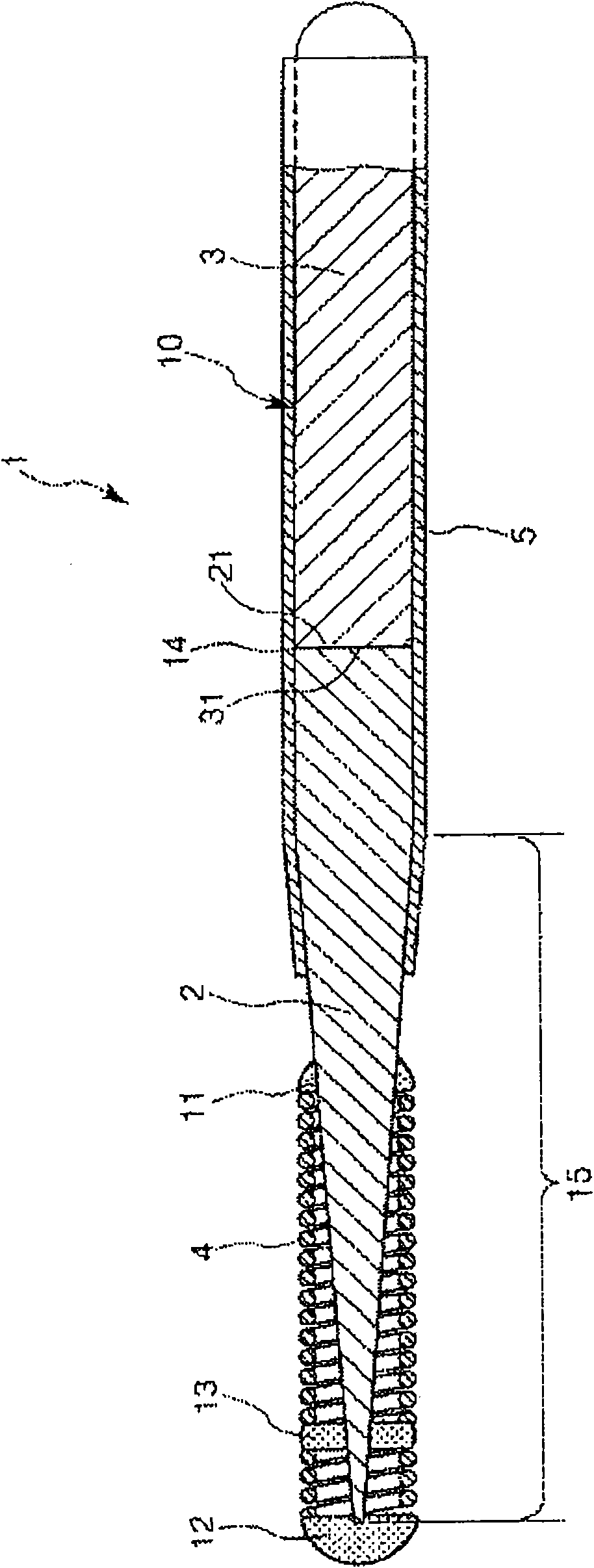
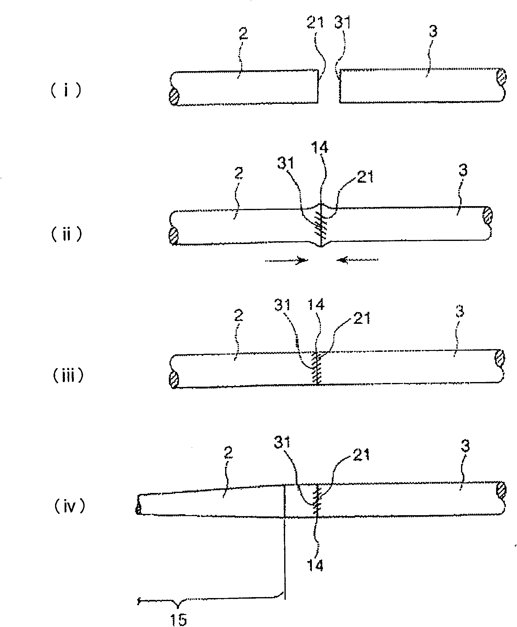
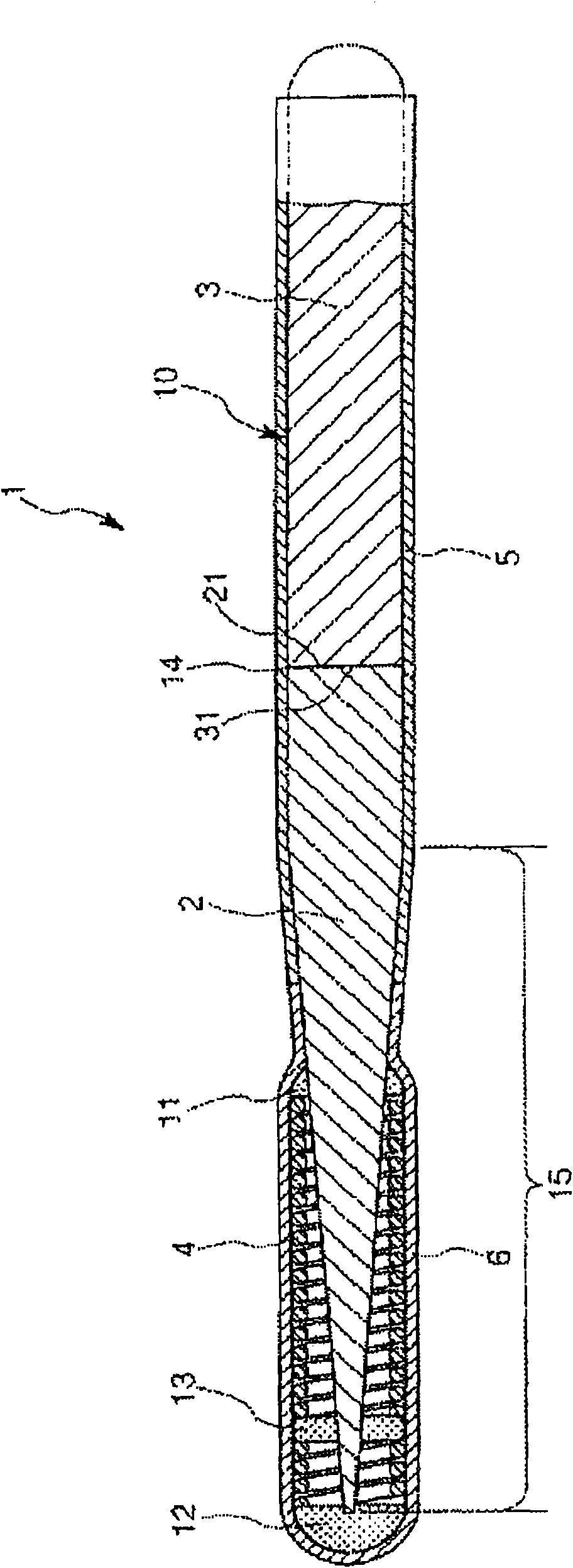
A guide wire that due to its wide elastic region and high Young's modulus, simultaneously has pliability and pushability, and that even when its surface is coated with a plastic material of high melting point, is highly impervious to influences of heat treatment, and that has excellent slidability and excels in weldability between a distal-end-side base material and a proximal-end-side core material. The guide wire has a core material comprising a distal-end-side core material and a proximal-end-side core material. The distal-end-side core material is made of an iron alloy having shape memorycapability and superelasticity, consisting essentially of two phases of gamma-phase and gamma'-phase and exhibiting, in a thermal hysteresis of martensite transformation and reverse transformation, adifference between reverse transformation completion temperature (Af-point) and martensite transformation starting temperature (Ms-point) of 100 DEG C or below. The proximal-end-side core material ismade of an alloy containing iron and has an elastic modulus higher than that of the distal-end-side core material. The distal-end-side core material and the proximal-end-side core material are weldedtogether.

Description

technical field [0001] The present invention relates to medical appliances. In particular, it relates to guide wires and stents inserted into body cavities such as blood vessels and bile ducts. Background technique [0002] Conventionally, in the examination and treatment of cardiac diseases and the like, a method has been adopted in which a guide wire is inserted into a target site and then a catheter (catheter) etc. is inserted along the guide wire. [0003] For example, in PCI (Percutaneous Coronary Intervention: Percutaneous Coronary Intervention), a branch of a coronary artery is first selected under X-ray fluoroscopy, and a guide wire is passed to a stenosis that is a target site. Then, the dilation catheter with the balloon at the tip is inserted into the body along the guide wire, and the balloon of the dilation catheter is positioned at the stenosis. Then, blood flow can be ensured just by inflating the balloon and pushing open the stenosis. In this way, angina p...

Claims


Application Information

Patent Timeline
Patent Type & Authority Applications(China)
IPC IPC(8): A61M25/01C22C19/07A61F2/82C22C38/00A61L31/00A61F2/91A61F2/915
CPCA61L31/10A61M25/09A61L2400/16A61F2230/0054A61L31/022A61M2025/09091A61F2230/005A61F2/915A61M2025/0915A61F2230/008A61F2002/9155A61F2/91Y10T29/4998Y10T29/49995
Inventor 石田清仁山内清贝沼亮介须藤祐司大森俊洋田中优树村山启早场亮一
Owner TERUMO KK
Why Eureka
Try Eureka