Two-stage integrative drying plant

A technology of drying equipment and drying chamber, which is applied to the device for coating liquid on the surface, printing, printing machine, etc. It can solve the problems of affecting product processing quality, short air blowing stroke, excessive energy consumption, etc., and achieves Effect of reducing low-temperature refrigeration demand, improving overall energy efficiency ratio, and high heat pump energy efficiency coefficient

Inactive Publication Date: 2010-05-12
VERBOCA ENERGY SAVING TECH CO LTD
View PDF2 Cites 6 Cited by
  • Summary
  • Abstract
  • Description
  • Claims
  • Application Information

AI Technical Summary

Problems solved by technology

However, this improvement scheme still has the following problems: 1. In order to control the cost of the device, the waste gas flow rate needs to be reduced, resulting in a more prominent explosion hazard; 2. In the process of waste gas treatment, a huge amount of additional energy is consumed, and the operating cost is high; 3. Activated carbon or activated carbon fiber is a consumable, which needs to be replaced regularly, resulting in an increase in cost and affecting production; 4. The desorption process will cause water pollution; the equipment is complex and bulky, occupying more valuable production sites, and causing more damage to the renovation project. 5. It does not help to improve product quality and avoid environmental impact on the production process
[0017] To sum up, the current drying equipment has the following disadvantages: 1. The drying gas enters and exits at the same time, which is difficult to meet the drying process requirements
2. The air blowing stroke is short, the air flow is small, the drying efficiency is low, the box is too long, and the control is difficult
3. Low heat utilization efficiency, excessive energy consumption and high operating costs
4. The air duct is complex and has many interfaces, the gas is easy to leak, the fan noise is loud, and the environmental protection is poor
5. The structure is complex, bulky, consumes a lot of steel, and the manufacturing cost is high
6. It is troublesome to install and transport, the cost is high, and it takes up a lot of space in the factory building
7. Organic solvents are harmful to the human body and the environment, and direct discharge will cause pollution
8. There are extremely economically valuable organic solvents and a large amount of heat in the exhaust gas, which cannot turn waste into treasure, resulting in high production consumption and reduced processing efficiency
9. In order to reduce the energy consumption of heating air, it is necessary to reduce the flow of fresh air, but it will cause the concentration of organic vapor to exceed the explosion limit and cause an explosion accident, which poses a serious safety hazard
10. A large amount of natural air is used, which makes the processing and production subject to the climate environment. When the ambient temperature is low, the energy consumption required for heating is huge, and even the drying needs cannot be met, resulting in production shutdown
11. The dust in the natural air affects the processing quality of the product

Method used


Image

  • Two-stage integrative drying plant
  • Two-stage integrative drying plant
  • Two-stage integrative drying plant

Examples


specific Embodiment 1

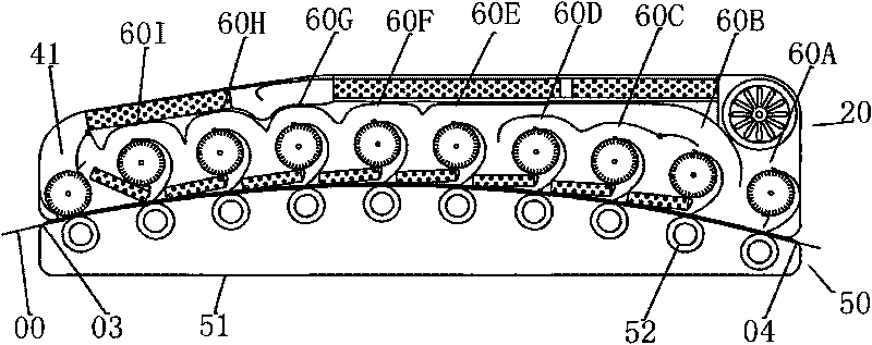
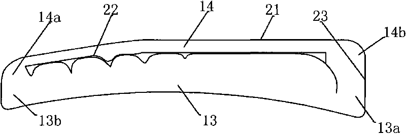
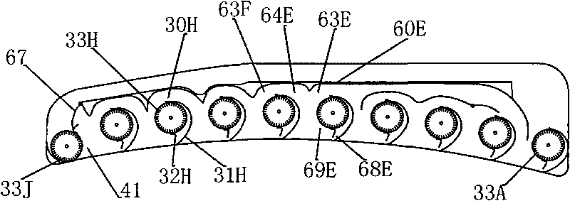
[0070] Figure 1 to Figure 9 Constitute the specific embodiment 1 of the present invention.

[0071] This embodiment is suitable for drying equipment for solvent printing machines.

[0072] Figure 1 to Figure 8 The detailed structure of the drying equipment described in this embodiment is provided, Figure 9 A schematic diagram of the heat pipe heat exchanger provided by the present invention is provided.

[0073] The corresponding relationship between component names and reference signs in each drawing is shown in Table 1.

[0074] Table 1: Correspondence between part names and reference signs

[0075] 00——Print 10——Oven 20——Oven cover

01——Fresh air inlet 11——Intake cavity 21——Cover parts

02——exhaust gas outlet 12——exhaust cavity 22——baffle parts

03——Print product inlet 13——Drying chamber 23——Frame parts

04——Print product outlet 14——Recovery cavity 24——Front beam

16——low temperature section 25——rear beam

...

specific Embodiment 2

[0111] This embodiment is suitable for drying equipment for solvent printing presses operating under extreme conditions.

[0112] Figure 10 , Figure 11 It is the accompanying drawing of specific embodiment 2 of the present invention, embodies the difference between this embodiment and specific embodiment 1 in that:

[0113] The fan 30K directly driven by the fan motor 38 is used as the circulation unit 41, and the return air damper moves accordingly.

[0114] The blower 30K adopts the large-diameter cross-flow impeller 33K to strengthen the circulating wind force.

[0115] The oven cover 20 is lengthened, and the drying unit 60J of the low-temperature section 16 is increased to increase the effective drying area.

[0116] The heat pump cooler 83B in the first embodiment is replaced by the heater 48, which is a PTC electric heater. Using the heater 48 can generate hot air over 100°C, meeting the extreme demands of the printing press.

[0117] Under normal circumstances, t...


PUM


Abstract

The invention relates to a two-stage integrative drying plant which is characterized by comprising an oven body (10), a drying unit (60) and a heat pump device (80), wherein the oven body (10) comprises a drying oven cover (20) and a base (50); a drying cavity (13) and a recovery cavity (14) which are mutually communicated are arranged in the drying oven cover (20); the drying unit comprises a fan (30) which is provided with an inlet channel (63), an exhaust channel (64) and an air outlet channel (68); the fan (30) is a tangential fan; the heat pump device (80) comprises a heat pump subcooler(82), a heat pump cooler (83), a middle cooler (84), a heat tube heat exchanger (95), a heat pump compressor (89), a heat pump throttling valve (87), a heat pump condenser (88), a cold compressor (99) and a refrigerant evaporator (96), wherein the cold compressor (99), the middle cooler (84), the heat pump compressor (89), the heat pump condenser (88), the heat pump throttling valve (87) and the refrigerant evaporator (96) are successively connected and loop the first and the last. The invention is suitable for processing equipment for continuous running thin strip objects and has the effectsof small volume, high efficiency and energy saving.

Description

technical field [0001] The invention relates to a two-stage integrated drying equipment, which is suitable for drying continuously traveling thin strip objects (hereinafter referred to as printed products), and is widely used in coating machines, compound machines, printing machines, roller coating lines, gluing machines, etc. Similar to processing equipment, it can also be used to dry continuously conveyed items. It belongs to the technical field of drying equipment such as printing and coating. Background technique [0002] At present, the equipment used for processing thin strip objects generally has the following characteristics: the printed product is a thin strip object that travels continuously, such as plastic film, thin metal plate, etc. in continuous processing. The surface of the processed product or product substrate is first covered with one or more layers of substances, such as ink, paint, glue, etc., using the transfer device of the equipment, and these subs...

Claims


Application Information

Patent Timeline
IPC IPC(8): B05D3/02B41F23/04
Inventor 简甦
Owner VERBOCA ENERGY SAVING TECH CO LTD
Why Eureka
Try Eureka