
Ceramic/metallic double continuous phase composite material brake pad and preparation method thereof

A dual continuous phase and composite material technology, applied in the direction of friction linings, mechanical equipment, etc., can solve the problems of short life, high cost, low performance of brake pads, etc., and achieve considerable economic and social benefits

Active Publication Date: 2013-01-16
INST OF METAL RESEARCH - CHINESE ACAD OF SCI
View PDF6 Cites 3 Cited by
  • Summary
  • Abstract
  • Description
  • Claims
  • Application Information

AI Technical Summary

Problems solved by technology

[0006] The purpose of the present invention is to provide a ceramic / metal bicontinuous phase composite brake pad for high-speed train braking and its preparation method, which solves the problems of low performance, short life and high cost of brake pads in the prior art

Method used

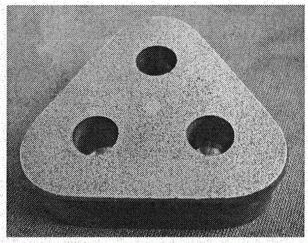
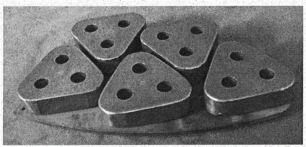
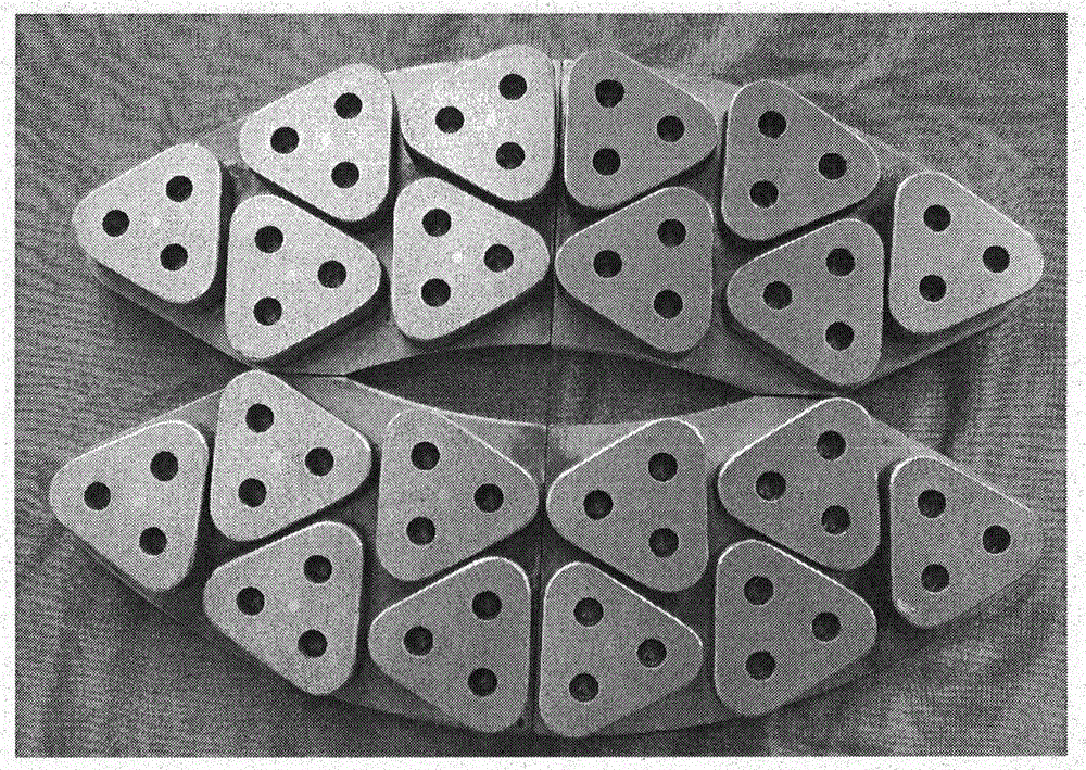

Image

  • Ceramic/metallic double continuous phase composite material brake pad and preparation method thereof
  • Ceramic/metallic double continuous phase composite material brake pad and preparation method thereof
  • Ceramic/metallic double continuous phase composite material brake pad and preparation method thereof

Examples


preparation example Construction

[0043] (2) Preparation and filling of friction components

[0044] Fe powder (35~300 mesh, 30~10%wt); SiO 2 Powder (35~200 mesh, 45~10%wt); Cr powder (35~300 mesh, 10~20%wt); Ni powder (100~300 mesh, 5~20%wt); Mo powder (100~300 Mesh, 5-15% wt); natural graphite powder (35-300 mesh, 0-25% wt), etc., weigh in proportion and mix, and add 5-15% wt of adhesive (water glass, silica sol, etc.) ; Mix uniformly and dry; use mechanical crushing and granulation through a 30-200 mesh sieve to obtain friction component particles; use mechanical vibration or suction injection to fill the friction component particles into the foam ceramic mesh.

[0045] (3) Connection of silicon carbide foam ceramic and steel back

[0046] The silicon carbide foam ceramic filled with friction components in the mesh is connected with the steel back by clamping or screw fixing.

[0047] (4) Preheating of silicon carbide foam ceramic framework steel back and melting of copper alloy

[0048] The silicon carbide foam ce...

Embodiment 1

[0058] First, the silicon carbide foam ceramics are prepared separately according to the method provided by the patent application number 03134039.3, wherein the size of the silicon carbide foam ceramics mesh is 0.8mm.

[0059] The composition of the friction component is shown in Table 1, and the mixture is evenly mixed and dried; the friction component particles are obtained by mechanical crushing and granulation through a 100-mesh sieve. The friction component particles are filled into the foam ceramic mesh by an oscillating method.

[0060] Table 1 The composition of the mixed particles of the table rubbing element

[0061] Edit

number

Ceramic foam

Mesh size

(mm)

Ceramic foam

Volume fraction

(%)

Silica

Micropowder g

(120~180 mesh)

Atomized iron powder g

(120~180 mesh)

Chromium powder g

300 mesh

Nickel powder g

300 mesh

Molybdenum powder g

300 mesh

Silicone

Sodium

ml

Leave

Zishui

ml

1

0.8

60

...

Embodiment 2

[0065] The difference from Example 1 is:

[0066] First, the silicon carbide foam ceramics are prepared separately according to the method provided by the patent application number 03134039.3, wherein the size of the silicon carbide foam ceramics mesh is 0.4 mm.

[0067] The composition of the friction component is shown in Table 2. After being evenly mixed, it is dried; mechanically crushed and granulated through a 120-mesh sieve to obtain friction component particles. The friction component particles are filled into the foam ceramic mesh by an oscillating method.

[0068] Table 2 Composition of friction component mixed particles

[0069] Edit

number

Ceramic foam

Mesh size

(mm)

Ceramic foam

Volume fraction

(%)

Silica

Micropowder g

(120~180 mesh)

Atomized iron powder g

(120~180 mesh)

Chromium powder g

300 mesh

Nickel powder g

300 mesh

Molybdenum powder g

300 mesh

Silicone

Sodium

ml

Leave

Zishui

ml

1

...


PUM

PropertyMeasurementUnit
pore sizeaaaaaaaaaa
particle sizeaaaaaaaaaa

Abstract

The invention relates to the field of friction materials for braking of high-speed trains, in particular to a ceramic / metallic double continuous phase composite material brake pad and a preparation method thereof. The brake pad comprises the following components in percentage by weight: 15 to 40 percent of foam silicon carbide ceramics, 10 to 30 percent of friction element and 75 to 30 percent ofmetal. The method comprises the following steps of: preparing the silicon carbide foam ceramics having a three-dimensional network structure by employing a technology combining polymer pyrolysis withcontrollable infiltration reaction sintering; selecting a proper friction element and filling in mesh holes of the foam ceramics; and injecting melt copper alloy into a framework of the foam ceramicsby utilizing an extrusion casting method to obtain the ceramic / metallic double continuous phase composite material brake pad. The composite material brake pad can be paired with a 28CrMoV forged steel brake disc, has the characteristics of proper and stable friction coefficient, low wear rate, high heat resistance, high thermal or mechanical damage resistance, good process performance, low manufacturing cost, long service life and the like, completely meets the brake requirement of a high-speed train at a speed of 200 to 300km / h, and has good competitive advantage on the brake requirement of a high-speed train at the speed of 350km / h.

Description

Technical field [0001] The invention relates to the field of friction materials for braking of high-speed trains, in particular to a ceramic / metal dual continuous phase composite brake pad composed of silicon carbide foam ceramics, friction components and copper alloy three-phase composites and a preparation method thereof. Background technique [0002] High-speed trains with speeds above 200km / h generally use disc brakes. When other braking methods of high-speed trains fail, disc brakes are the only guarantee for safe train stopping. Therefore, the disc brake is a key component of high-speed trains and an important guarantee for safe operation. The study of its key material-advanced braking materials has naturally become an important work in the research of braking devices. It is for this reason that France, Germany, and Japan all use disc brake friction materials as a key technology when developing high-speed railways. At present, my country is also introducing and researching...

Claims


Application Information

Patent Timeline
Patent Type & Authority Patents(China)
IPC IPC(8): F16D69/02
Inventor 张劲松曹小明张宇南田冲杨振明
Owner INST OF METAL RESEARCH - CHINESE ACAD OF SCI
Learn More