

Electron beam ablation propulsion method and system
A technology of electron beam and high-current electron beam, which is applied in the field of electron beam ablation propulsion method and system, can solve the problems of shallow interaction depth between laser and material, low energy utilization rate of thruster, and limitation of thruster target selection, etc., to achieve The effect of small ablation beam spot, large total stroke and long service life
- Summary
- Abstract
- Description
- Claims
- Application Information
AI Technical Summary
Problems solved by technology
Method used
Image

Examples
Embodiment 1
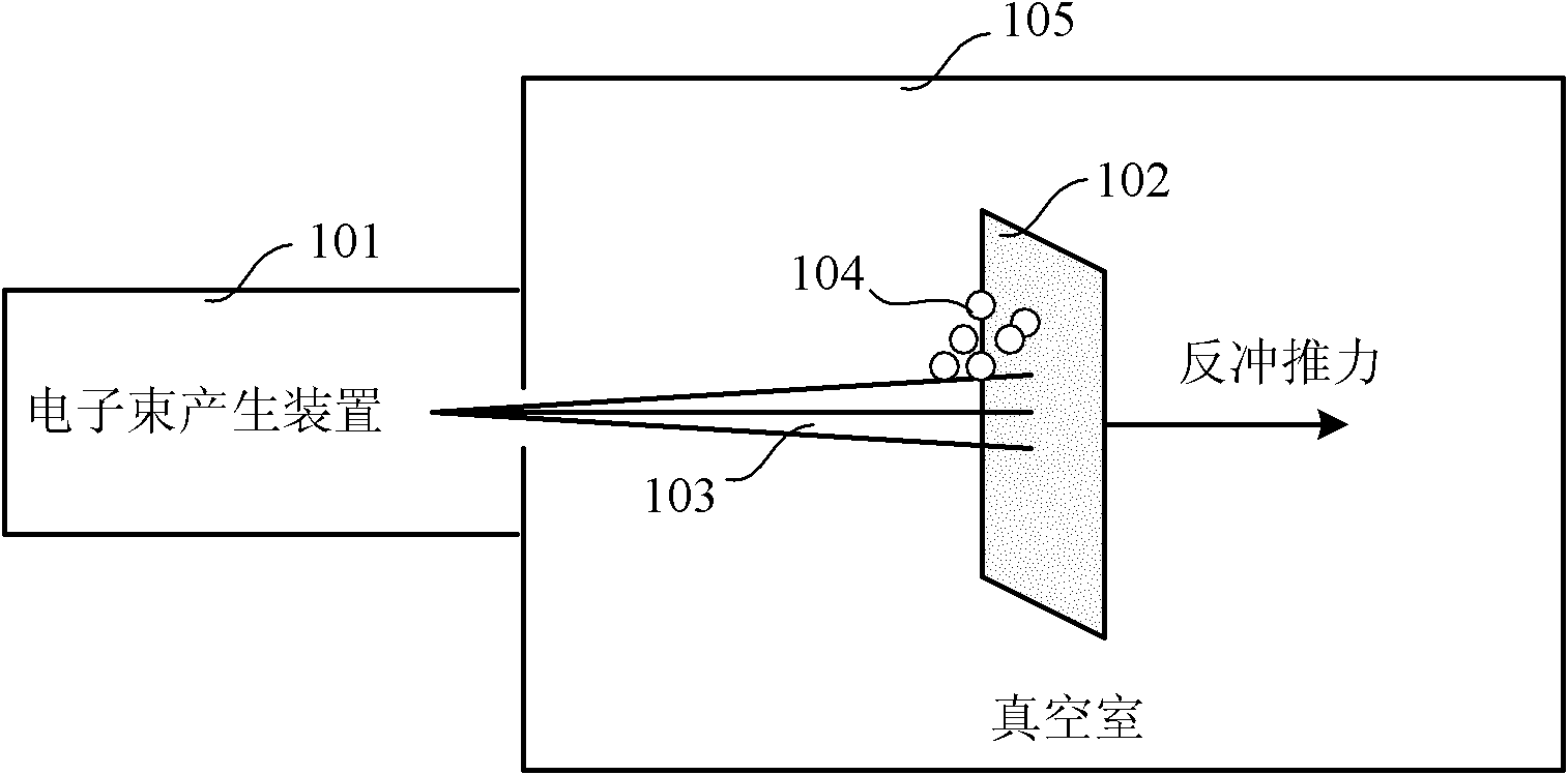
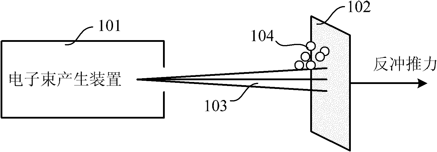
[0018] As shown in FIG. 1 , the electron beam ablation propulsion system of this embodiment includes: an electron beam generating device 101 and a target 102 .
[0019] The electron beam generating device 101 generates electron beams, and makes the electron beams pass through the exit of the electron beam generating device 101 and shoot toward the target 102 to generate ablation recoil thrust along the electron beam transmission direction. The target 102 receives the electron beam generated by the electron beam generating device 101 , and generates gas or tiny particles outward (opposite to the direction of electron beam transmission) under the ablation effect of the electron beam. The material of the target 102 may be gold, silver, copper, aluminum, etc., and the present invention is not limited thereto.
[0020] The electron beam ablation propulsion system of this embodiment can also be as Figure 1B as shown, Figure 1B and Figure 1A The difference is that the target is ...
Embodiment 2
[0038] Such as Figure 4 As shown, the present embodiment provides an electron beam ablation advancing method, the method comprising:
[0039] Using an electron beam generating device to generate an electron beam, and causing the electron beam to pass through the exit of the electron beam generating device to the target S401;
[0040] The electron beam ablates the target material to generate recoil thrust to push the target material, that is, the electron beam ablates the target material, causing the target material to eject gas or tiny particles outward, and at the same time generate a reaction force. Impact thrust; the recoil thrust pushes the target S402.
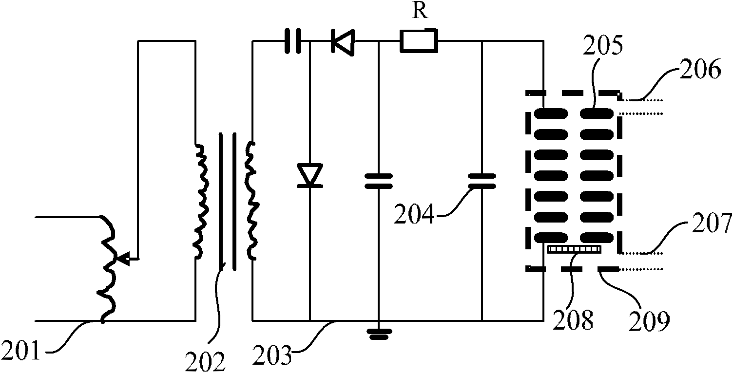
[0041] The electron beam generating device 101 can be a short-pulse high-current electron beam generating device, including: Marx generator-pulse forming line-multistage discharge chamber, trigger-single-stage discharge chamber, pseudo-spark discharge device, etc. The present invention only uses pseudo-spark The spark ...
PUM
| Property | Measurement | Unit |
|---|---|---|
| Outer diameter | aaaaa | aaaaa |
| The inside diameter of | aaaaa | aaaaa |
| Thickness | aaaaa | aaaaa |
Abstract
Description
Claims
Application Information