Middle-infrared waveband transmission type sub-wavelength metal grating

A metal grating and infrared band technology, applied in the direction of diffraction gratings, waveguide devices, electrical components, etc., can solve the problem that the infrared window can only transmit waves and cannot filter, etc., and achieves strong controllability of band-pass performance, easy implementation, The effect of high transmittance

Inactive Publication Date: 2012-04-04
UNIV OF ELECTRONICS SCI & TECH OF CHINA
View PDF3 Cites 17 Cited by
  • Summary
  • Abstract
  • Description
  • Claims
  • Application Information

AI Technical Summary

Problems solved by technology

[0007] The technical solution of the present invention: Aiming at the technical defect that the current infrared window can only transmit waves but not filter, a mid-infrared band transmissive sub-wavelength metal grating is proposed

Method used


Image

  • Middle-infrared waveband transmission type sub-wavelength metal grating
  • Middle-infrared waveband transmission type sub-wavelength metal grating
  • Middle-infrared waveband transmission type sub-wavelength metal grating

Examples


example 1

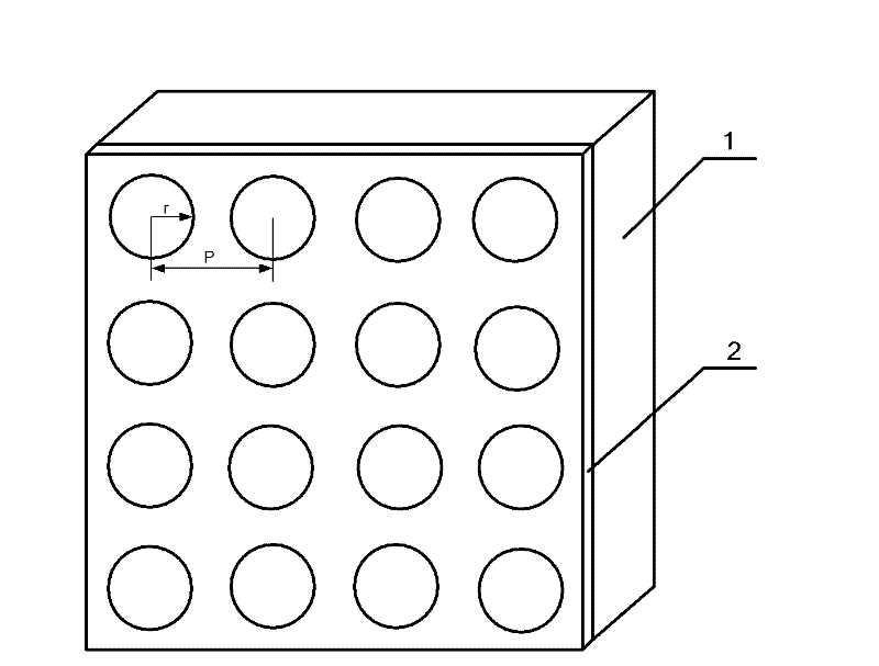
[0024] Example 1. Taking the hole structure on the metal aluminum film as a square array arrangement, the hole period is 6 microns, and the hole diameter is 3 microns as an example:

[0025] ① Clean the substrate, use acetone, alcohol, and deionized water to ultrasonically clean the substrate in sequence, and the ultrasonic cleaning time for each step is about 10 minutes;

[0026] ② Spin-coat AZ5214 reverse photoresist with uniform thickness on the surface of the cleaned substrate by using a glue spinner;

[0027] ③Use a baking board to pre-bake the glue-coated substrate at a temperature of 100 degrees Celsius for 1 minute;

[0028] ④Use a contact type ultraviolet exposure machine to expose the coated substrate, and transfer the periodic hole array pattern on the mask plate to the photoresist under the ultraviolet light source, and the exposure time is 2.5 seconds;

[0029] ⑤ Post-baking the exposed substrate with a baking plate to convert the negative photoresist into a posi...

example 2

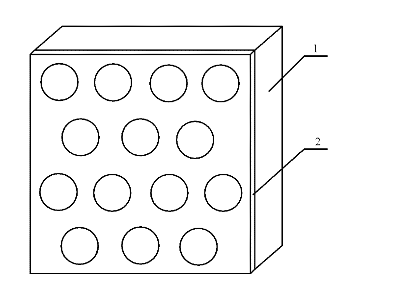
[0034] Example 2. Take the hole structure on the metal aluminum film arranged in a hexagonal array, the array period is 6 microns, and the hole diameter is 3 microns as an example:

[0035] Except step ④, other steps are the same as Example 1. In this example, the patterns on the photolithography mask used in step ④ are arranged in a hexagonal hole array structure.

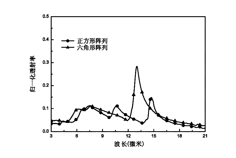
[0036] For the above two mid-infrared band transmissive sub-wavelength metal grating samples, the infrared transmittance curves were tested by Fourier transform infrared spectrometer, as shown in image 3 As shown: the metal grating with the hexagonal array structure achieves a transmission peak with a transmittance of about 30% at 12 to 15 microns (about 2.2 times the array period), and the metal grating with the square array structure at 13 to 16 microns (about 2.2 times the array period). 2.5 times the array period), a transmission peak with a transmittance of about 18% is realized.


PUM

PropertyMeasurementUnit
thicknessaaaaaaaaaa
thicknessaaaaaaaaaa

Abstract

The invention discloses a middle-infrared waveband transmission type sub-wavelength metal grating, which belongs to the technical field of function material and device. The metal grating comprises a zinc selenide glass substrate and a metal film which is located on the surface of the zinc selenide glass substrate and is provided with a periodicity hole structure; and in the periodicity hole structure, radius r of single hole is smaller than 1/2 of hole period P, and the hole period P is 1-10mu. The middle-infrared waveband transmission type sub-wavelength metal grating uses a sub-wavelength periodicity structure of less than infrared wavelength to realize selective transmission of infrared rays in the middle-infrared waveband of 2.5-25mu, and meanwhile shields the function of microwave millimeter waveband electromagnetic wave. The middle-infrared waveband transmission type sub-wavelength metal grating has the characteristics of simple structure and easy implementation, and can be applied to infrared detection device requiring electromagnetic shielding.

Description

technical field [0001] The invention belongs to the technical field of functional materials and devices, and is applied to the field of infrared optical devices such as a selective wave-transmitting detection window with electromagnetic shielding function in the mid-infrared band and a band-pass filter. Background technique [0002] Currently, in the field of application of infrared detection windows, an optical window that can effectively shield electromagnetic interference and transmit infrared light is needed. Most of the current applications use the structure of metal grids to realize the above functions. The period of this metal grid structure is much longer than the wavelength of infrared light, and has little effect on the performance of infrared optical band. [0003] The research on subwavelength metal periodic structures originated from the end of last century, and a new discipline derived from it: surface plasmonics (plasmonics), has become a research hotspot in ...

Claims


Application Information

Patent Timeline
Patent Type & Authority Applications(China)
IPC IPC(8): G02B5/18H01P1/20
Inventor 周佩珩张楠谢建良邓龙江
Owner UNIV OF ELECTRONICS SCI & TECH OF CHINA
Why Eureka
Try Eureka