Micropore forming method

A forming method and microporous technology, applied in the field of instrumentation (analytical instruments), can solve the problems of reducing processing accuracy, human injury, and damage to tool life, etc., and achieve the effect of easy implementation, simple method, and improved processing accuracy

Inactive Publication Date: 2012-07-25
KYKY TECH
View PDF6 Cites 12 Cited by
  • Summary
  • Abstract
  • Description
  • Claims
  • Application Information

AI Technical Summary

Problems solved by technology

[0005] However, the above method has the following disadvantages: ①Using the laser cutting method to process the molybdenum thin sheet diaphragm can meet the precision requirements, but it needs to pre-configure hardware equipment such as ultraviolet lasers and computers and build corresponding workbenches and scanning galvanometer systems. The equipment investment is large, and the post-maintenance cost is also high, which leads to a substantial increase in the manufacturing cost of the molybdenum thin film diaphragm; It may cause cancer, and the ultraviolet laser is also very harmful to the eyes. Therefore, when the operator uses the above method to process the molybdenum sheet, even if the necessary safety protection measures are taken, the ultraviolet laser may cause harm to the human body.
Although grease lubricant can provide a good lubricating effect, its cleaning effect and cooling effect are far inferior to cutting

Method used


Image

  • Micropore forming method
  • Micropore forming method
  • Micropore forming method

Examples


Embodiment 1

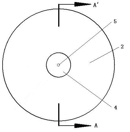
[0046] Such as Figure 3-4 As shown, it is a schematic diagram of a molybdenum sheet 2 as an electron microscope suction pole. The design diameter of the molybdenum sheet 2 is Ф30mm, and the design thickness is 0.5mm, and a diameter of Ф0 should be formed at the center of the molybdenum sheet 2. .38mm, roundness of 0.01mm, and surface roughness of Ra0.1 micropore 5, that is, the extremely small hole for suction.

[0047] In the present invention, the so-called "design diameter of the molybdenum flake 2" refers to the diameter requirement that the molybdenum flake as the electron microscope extractor should meet. The so-called "design thickness of the molybdenum sheet 2" refers to the thickness requirement that the molybdenum sheet used as the electron microscope extraction electrode should meet.

[0048] The processing steps of forming the micropores 5 on the molybdenum sheet 2 using the micropore forming method provided by the present invention include:

[0049] ① Turn the ...

Embodiment 2

[0061] Compared with Embodiment 1, the processing steps of forming micropores 5 on the molybdenum sheet 2 in the present embodiment include:

[0062] ① The workpiece is fixed, and the molybdenum sheet 2 is fixed on the workbench of the processing equipment. In this embodiment, the processing equipment is a processing center with a series of common processing machine tools such as lathes and drilling machines.

[0063] ② micropore forming, forming the micropore 5 with a diameter of Ф0.38mm, a roundness of 0.01mm, and a surface roughness of Ra0.1 at the predetermined position of the molybdenum sheet 2. In this embodiment, the The predetermined position is the center position of the molybdenum sheet 2 . The specific steps are as follows:

[0064] a. Utilize a positioning drill to form a positioning hole on the predetermined position of the molybdenum sheet 2;

[0065] b. Using a drill bit with a diameter of Ф0.28 mm to Ф0.32 mm, forming a pre-drilled hole along the thickness d...

Embodiment 3

[0069] The difference between this embodiment and Embodiment 1 is: in the step c of the 5th step, the rotating speed of the reaming drill is 5000 revolutions / min, the feed rate is 5mm / min, and the number of cycle drilling times is 12 times, and increase the supply of cutting fluid and the amount of grease lubricant applied.

[0070] The molding method provided by the invention can appropriately reduce the requirements on processing equipment and avoid extra equipment investment. For example, when using some relatively old or low-precision processing equipment for micro-hole processing, since these processing equipment may not be able to reach a high speed such as 7500 rpm, it is also impossible to control the reaming drill to stabilize at a low speed of 3mm / min. Feed, then at this time, the speed of the reaming drill can be appropriately reduced and the feed speed can be increased. Although, lower rotational speed and faster feed rate are not conducive to the formation of mic...


PUM

PropertyMeasurementUnit
Diameteraaaaaaaaaa
Depthaaaaaaaaaa
Diameteraaaaaaaaaa

Abstract

A micropore forming method includes the steps: firstly, fixing a molybdenum sheet on a worktable of machining equipment; and secondly, forming a micropore with the diameter of phi 0.38mm, the roundness of 0.01mm and the surface roughness of Ra 0.1 at a preset position of the molybdenum sheet. The micropore forming step particularly includes positioning, pre-drilling and expanding. An expanding drill with the diameter of phi 0.38mm is used for expanding on the basis of pre-drilling during expanding, cutting fluid is used for washing the expanding drill and the molybdenum sheet during expanding, the rotation speed of the expanding drill is 5000-10000 revolutions per minute, the feed speed of the expanding drill is 1-5mm/min, drilling is repeated for 8-12 times, and grease lubricant is smeared on the surface of a drill bit of the expanding drill. The micropore forming method adopts a machining mode, and the formed micropore can meet the requirement of an extremely small suction hole on machining precision.

Description

technical field [0001] The invention relates to the field of instrumentation (analytical instrument), in particular to a method for forming micropores on a molybdenum sheet of an electron microscope. Background technique [0002] The electron gun of the field emission electron microscope is a tiny high-brightness electron source, which consists of a tungsten single crystal (W (100)) coated with zirconia (ZrO) Schottky emission cathode or cold field emission cathode, suppression pole, extraction pole, focusing Its function is to provide a stable electron source for the whole system. When the surface of the tip of the cathode tungsten wire in vacuum is subjected to 10 8 When electrons with a size of V / cm are accelerated by an electric field, a considerable number of electrons will be emitted from the surface of the tungsten tip. This process is called field emission. The principle of field emission is that a high electric field causes the potential barrier of electrons to pr...

Claims


Application Information

Patent Timeline
IPC IPC(8): B23B35/00
Inventor 张景云杜建麻建平刘亚琪
Owner KYKY TECH
Why Eureka
Try Eureka